
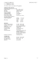


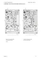

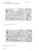


2 CIRCUIT DESCRIPTION
RT2047 DSC - PART II
PAGE 2-1
2
CIRCUIT DESCRIPTION
2.1
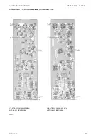
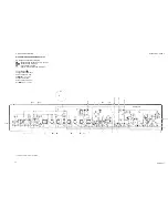
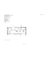
RECEIVER UNIT MODULE 100
The receiver unit includes the following circuits:
2.1.1
RF-AMPLIFIER AND FIRST MIXER
The RF-amplifier working in the frequency range 155.4 MHz to 162.4 MHz consists of the transistor Q101
and the two double-tuned filters surrounding it. The signal is led from the aerial through the duplex-filter
to the antenna switch and from there to the receivers input-filter. The input filter and the intermediate filter
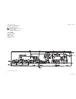
are variable capacitance tuned filters, controlled by a DC-voltage derived from the RX-VCO control
voltage. This secures an optimal filter response within the receivers frequency range. The two double-
tuned filters create the necessary attenuation of signals distant from the wanted signal frequency in order
to give the wanted spurious rejection of such unwanted signals. The amplifying transistor Q101 (which
is a large current, low noise transistor in a common-base configuration) secures by its gain the receiver
overall noise figure and a good two-signal performance. The RF-input to the first mixer is taken from the
coil L104 in the intermediate filter. Mixer transistor Q102 is of the JFET-type, where the first LO-signal
is injecting into the source from a 50 ohm generator. The wanted 21.4 MHz IF-output is selected by means
of the tuned drain circuit consisting of L105, C117, C119, and R110 which also creates the necessary
impedance matching the IF-crystal filter.
2.1.2
IF-FILTER AND AMPLIFIER
The receivers adjacent channel selectivity is maintained by means of the crystal filter FL101. The output
from this filter is led to the IF-amplifier with the transistor Q103, L106, C123, and R112 giving the
appropriate impedance matching the filter output. The amplifier gives the needed power gain between
the crystal filter and the second mixer and also secures good large signal performance.
2.1.3
SECOND MIXER, CERAMIC FILTER, DETECTOR AND AF AMPLIFIER
The integrated IF circuit includes the second mixer, the limiting amplifier and the detector with post AF
amplifier.
The second local oscillator signal is generated by means of the integrated oscillator and an external
crystal X101, running on 20.945 MHz. The signal out of the second mixer (455 kHz) is fed through the
ceramic filter FL102 to the limiting amplifier and discriminator in U101.
The quadrature phase discriminator includes the external phase shift network consisting of the tank circuit
with L108, C129 and R120.
The AF output from the detector is amplified by means of an internal operational amplifier and finally
buffered by means of the discreet transistor amplifier with Q104.
2.1.4
IF POWER SUPPLY
The integrated IF circuit and AF buffer amplifier are powered from an integrated 5V series voltage
regulator U102. The input voltage for this circuit is the receiver 10V supply.
9543
Содержание RT2047
Страница 1: ...S P RADIO A S AALBORG DENMARK TECHNICAL MANUAL FOR COMPACT VHF RT2047 D ...
Страница 2: ......
Страница 5: ...RT2047 DSC PART I CONTENTS 1 GENERAL INFORMATION 1 1 1 1 INTRODUCTION 1 1 ...
Страница 6: ......
Страница 8: ......
Страница 10: ......
Страница 24: ......
Страница 30: ...1 GENERAL INFORMATION RT2047 DSC PART II PAGE 1 6 9543 ...
Страница 32: ......
Страница 34: ......
Страница 46: ...2 CIRCUIT DESCRIPTION RT2047 DSC PART II PAGE 2 12 9543 ...
Страница 50: ...2 CIRCUIT DESCRIPTION RT2047 DSC PART II 9543 PAGE 2 16 ...
Страница 66: ...9546 ...
Страница 67: ...2 CIRCUIT DESCRIPTION RT2047 DSC PART II 9546 PAGE 2 33 32162 ...
Страница 81: ......
Страница 82: ......
Страница 84: ......
Страница 85: ...PAGE 3 1 9545 3 MECHANICAL DISASSEMBLING AND MODULE LOCATION 3 1 MECHANICAL DISASSEMBLING RT2047 DSC PART II ...
Страница 86: ...3 MECHANICAL DISASSEMBLING AND MODULE LOCATION RT2047 DSC PART II PAGE 3 2 9545 ...
Страница 88: ......
Страница 90: ......
Страница 98: ...4 SERVICE RT2047 DSC PART II PAGE 4 8 9545 ...
Страница 99: ...4 SERVICE RT2047 DSC PART II 4 11 PIN CONFIGURATION 9545 PAGE 4 9 ...
Страница 101: ...4 SERVICE RT2047 DSC PART II NMC93C56N PIN ARRANGEMENT BLOCK DIAGRAM LM393N PIN ARRANGEMENT PAGE 4 11 9545 ...
Страница 109: ...RT2047 DSC PART II CONTENTS 5 PARTS LISTS 5 1 9546 ...
Страница 110: ......
Страница 124: ......


