


Parameter description
Specification of SN200G high-performance vector convertor
- 72 -
function input terminal 18 is (frequency switch) valid, auxiliary frequency source Y is target frequency.
3: Switch of main frequency source X and main & auxiliary operation result. When multi-function
input terminal 18 is (frequency switch) invalid, main frequency source X is target frequency. When multi-
function input terminal 18 is (frequency switch) valid, main & auxiliary operation result is target
frequency.
4. Switch of auxiliary frequency source Y and main & auxiliary operation result. When multi-
function input terminal 18 is (frequency switch) invalid, auxiliary frequency source Y is target frequency.
When multi- function input terminal 18 is (frequency switch) valid, main & auxiliary operation result is
target frequency.
Ten bit: Main and auxiliary frequency source operational relationship:
0: Main frequency source X + auxiliary frequency source Y
Sum of main frequency X and accessorial frequency Y is used as the target frequency. Achieve
frequency superposition given feature.
1: Main frequency source X- auxiliary frequency source Y
The difference between main frequency source X and auxiliary frequency source Y is used as target
frequency.
2: MAX (Main frequency source X, the auxiliary frequency source Y) Take the maximum absolute
value of main frequency X and accessorial frequency Y as the target frequency.
3: MIN (Main frequency source X, the auxiliary frequency source Y) Take the minimum absolute
value of main frequency X and accessorial frequency Y as the target frequency. In addition, When the
frequency source selection is main and auxiliary operations, offset frequency can be set by P0-21. Offset
frequency superimposed on the main and auxiliary operation result to respond flexibly to various needs.
4: MIN (Main frequency source X, the auxiliary frequency source Y) Take the minimum absolute
value of main frequency X and accessorial frequency Y as the target frequency. In addition, When the
frequency source selection is main and auxiliary operations, offset frequency can be set by P0-21. Offset
frequency superimposed on the main and auxiliary operation result to respond flexibly to various needs.
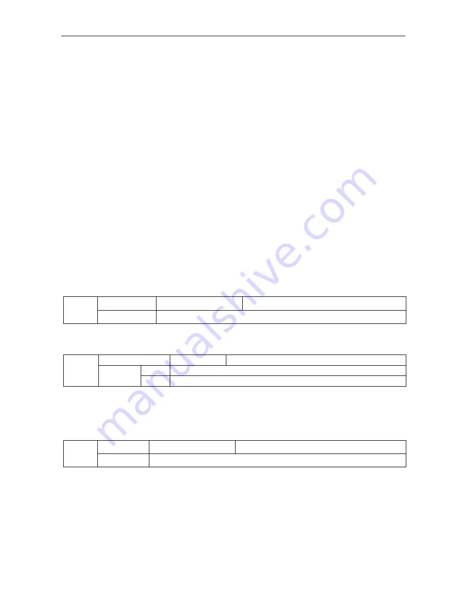
P0-08
Preset frequency Factory default
50.00Hz
Setting range
0.00
~
max. frequency (frequency source selection mode to digital setting is effective)
When the frequency source is selected for the “Digital setup” or “terminal UP / DOWN”, the digital
frequency inverter function code is the initial setting value.
P0-09
Running direction
Factory default
0
Setting
range
0
Same direction
1
Opposite direction
By changing the function code, it can not change the electrical wiring and achieve the purpose of
changing the motor rotation. Which acts to adjust the motor (U, V, W) to convert any two lines of the
motor rotation direction.
Prompt: After initialization of parameter, motor running direction will restore the original state. Be
caution to use it in the condition that after the system is debugged, the motor steering is strictly prohibited
to change.
P0-10
Max. frequencyFactory default
50.00 Hz
Setting range
50.00Hz
~
600.00Hz
SN200G analog input, pulse input (DI5), multi-step instructions, etc., as the frequency source is
100.0% relative to the respective scaling P0-10.
SN200G maximum output frequency is up to 3200Hz. As to take into account for the frequency
resolution and frequency input range for both indicators, it may select frequency instruction decimal
places by P0-22.
When P0-22 is selected as 1, the frequency resolution is 0.1Hz. In this case P0-10 is set in the range
of 50.0Hz ~ 3200.0Hz;
When P0-22 is selected as 2, the frequency resolution is 0.1Hz. In this case P0-10 is set in the range
of 50.0Hz ~ 600.00Hz.


