


5
START-UP
5-2
004AZ011B
5.2.2
START-UP PROCEDURE
The following operations need to be carried out for each image shooting station:
1 Activate the main switch on the main electrical cabinet: look at the screen to make sure the PC start-up operations
are correct and that no warning or error messages appear.
2 Place a product to be inspected under the image shooting station.
3 Using the continuous capture function, make sure the image shooting stations work properly. Adjust as required
with the controls provided and make sure the image of the product to be inspected is seen.
4 Adjust the camera, lens and lighting units as required to reproduce the factory testing conditions.
5 Capture defect-free and defective products to check the efficiency of the configuration employed. Use the
asynchronized command to capture the images.
6 After being sure that the configuration is efficient, adjust the guides and presence sensor. Capture images of
moving pieces using the synchronized capture command.
7 Once the correct capture of the moving image has been obtained, adjust the ejection station position, the ejection
position parameter and the ejection duration parameter. Make sure the ejection station is operating properly by
checking the air pressure values.
8 If the reject control sensor is provided, adjust the position and tolerance with the parameters provided.
Remember that when the electronic equipment is employed to handle various product sizes or when the image
shooting station needs to be adjusted, operations 4, 5, 6, 7, 8 have to be repeated entirely or in part.
Read the attached user manual for further details as indicated in chapter 1 - GENERAL INFORMATION, paragraph
ATTACHMENTS.
D0003275_00
NOTICE
The basic functions of the SACMI inspection software should be know so as to perform the indicated operations.
Содержание CVS Series
Страница 2: ......
Страница 4: ...004AZ011B...
Страница 8: ...004AZ011B TABLE OF CONTENTS Page 0 8...
Страница 16: ...004AZ011B 1 GENERAL INFORMATION 1 8...
Страница 37: ...T6912 SAFETY EQUIPMENT AND PRECAUTIONS 3 3 3 004AZ011B FIGURE 3 1 2 LOCKOUT TAGOUT QS1...
Страница 46: ...3 SAFETY EQUIPMENT AND PRECAUTIONS 3 12 004AZ011B...
Страница 52: ...UPS T6785 4 INSTALLATION 4 6 004AZ011B FIGURE 4 3 1 1 CONNECTING THE ELECTRIC CABLES 1 3 2 4 CAMERA LINK...
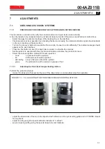
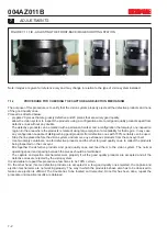
Страница 62: ...7 ADJUSTMENTS 7 4 004AZ011B...
Страница 66: ...8 MAINTENANCE 8 4 004AZ011B...


