


004AZ011B
2
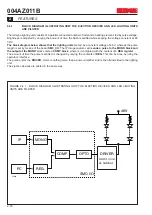
FEATURES
2-10
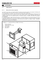
2.1.1.7
Auxiliary equipment
The term “auxiliary equipment” refers to all the control devices, generally sensors and actuators, connected to the
switchboard that carry out auxiliary functions.
For more detailed information, consult chapter 6 - USE OF THE ELECTRONIC EQUIPMENT.
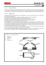
2.1.1.7.1
Image shooting sensors
As explained in chapter 6 - USE OF THE ELECTRONIC EQUIPMENT, introduction to the CVS, a sensor that starts
the inspection process has to be installed. This sensor detects the position of the pieces being inspected. According
to the type of objected to be inspected, optoelectronic sensors, like projector photocells or reflection photocells, or
sensors based on magnetic or capacitive principles can be used.
The image shooting sensor is usually installed next to the image shooting station, and therefore is inside the image
shooting box: for connection see chapter 1 - GENERAL INFORMATION, paragraph ATTACHMENTS.
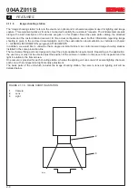
2.1.1.7.2
Ejection stations
A solenoid valve is used to eject defective pieces. This valve can either control pneumatic pistons or directly work on
the pieces by means of nozzles. The shape and setting of nozzles is related to the type of object to be ejected. The
set of solenoid valve, ejection mechanical system and fastening supports is defined ejection station. For connections
see chapter 1 - GENERAL INFORMATION, paragraph ATTACHMENTS.
2.1.1.7.3 Encoders
The space between the ejection station and image shooting sensor remains unchanged. When the CVS is installed
on the conveyor belt, an incremental encoder is fastened to the drive shaft of the conveyor for tracking the inspected
pieces and if piece sliding is zero on the belt. In this manner pieces are always ejected in the same position. For
connections see chapter 1 - GENERAL INFORMATION, paragraph ATTACHMENTS.
2.1.1.7.4
Indicator tower
An indicator tower is installed next to the image shooting station and lights of different colors indicate the state of the
machine: yellow = stopped, green = inspection, blue = alarm.
Содержание CVS Series
Страница 2: ......
Страница 4: ...004AZ011B...
Страница 8: ...004AZ011B TABLE OF CONTENTS Page 0 8...
Страница 16: ...004AZ011B 1 GENERAL INFORMATION 1 8...
Страница 37: ...T6912 SAFETY EQUIPMENT AND PRECAUTIONS 3 3 3 004AZ011B FIGURE 3 1 2 LOCKOUT TAGOUT QS1...
Страница 46: ...3 SAFETY EQUIPMENT AND PRECAUTIONS 3 12 004AZ011B...
Страница 52: ...UPS T6785 4 INSTALLATION 4 6 004AZ011B FIGURE 4 3 1 1 CONNECTING THE ELECTRIC CABLES 1 3 2 4 CAMERA LINK...
Страница 62: ...7 ADJUSTMENTS 7 4 004AZ011B...
Страница 66: ...8 MAINTENANCE 8 4 004AZ011B...


