Saab R5 SUPREME MkII Скачать руководство пользователя страница 1


OPERATION & INSTALLATION MANUAL 


Saab AB (publ), TransponderTech 

R5 SUPREME


Navigation System 

MkII 

Содержание R5 SUPREME MkII

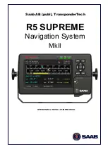
Страница 1: ...OPERATION INSTALLATION MANUAL Saab AB publ TransponderTech R5 SUPREME Navigation System MkII...

Страница 2: ...This page is intentionally empty...

Страница 3: ...ile reasonable care has been exercised in the preparation of this manual Saab AB publ TransponderTech shall incur no liability whatsoever based on the contents or lack of contents in the manual iii So...

Страница 4: ...tion For installation service ordering info and technical support please contact your local Saab AB publ TransponderTech representative A list of dealers and service stations can be found on the corre...

Страница 5: ...llation Cables 15 5 4 System interconnection overview 16 5 5 Installation Procedure 18 5 6 Mount the R5 SUPREME Control and Display Unit CDU 19 5 7 Mount the R5 Navigation Sensor 23 5 8 Mount the GNSS...

Страница 6: ...de R5 Navigation Sensor Software 119 12 3 Save Load Config to from USB memory 121 12 4 Factory reset 125 13 Troubleshooting 126 13 1 Troubleshooting with the CDU Front Panel LEDs 126 13 2 Troubleshoot...

Страница 7: ...53 18 3 Internal Alarm Relay 154 19 Electrical Interfaces 155 19 1 CDU Interfaces 155 19 2 R5 Navigation Sensor interfaces 158 20 Mechanical Drawings 164 20 1 CDU Physical Size and Mechanical Drawing...

Страница 8: ...d A power supply corresponding to the voltage rating of the equipment shall be used Failure to comply with this requirement may damage the equipment To ensure proper functioning of the equipment only...

Страница 9: ...ation System MkII MAIN SYSTEM COMPONENTS 7000 118 383 B1 Page 9 2 MAIN SYSTEM COMPONENTS NOTE Delivered items may vary depending on customer choice R5 Navigation Sensor D GNSS Antenna R5 SUPREME Contr...

Страница 10: ...isplay and provides a graphical interface to the system Via the R5 CDU it is possible to create edit and modify routes and waypoints navigate following a route plot the route view sensor data configur...

Страница 11: ...ontrol Supports combined Nav R5 Supreme AIS transponder operation USB service port Route Navigation Route Logging to SD card memory Capability to handle and store up to 4000 individually named waypoin...

Страница 12: ...f a route between two consecutive waypoints A route with the waypoints A B and C has two legs A to B and B to C For each leg in a route the navigation algorithm RAIM accuracy level and cross track err...

Страница 13: ...jected chart and cuts across all meridians at the same angle Waypoint Pass Criterion The criterion used to determine when a waypoint in the active route is considered passed The waypoint pass criterio...

Страница 14: ...ilable parts NOTE This is not a list of supplied parts as contents may vary for each order depending on user needs Name Part number R5 SUPREME CDU 7000 118 530 R5 Power Cable 7000 118 077 Navigation S...

Страница 15: ...posed 5 3 Installation Cables The following cables are used to install the standard R5 SUPREME Navigation System R5 Power Cable Marking 7000 118 077 Application R5 CDU power port to R5 NAV Junction bo...

Страница 16: ...p in a number of different ways As a standalone navigation system o One CDU unit one sensor one antenna As a Combined Navigation and AIS system o Same as above plus a transponder with additional D GNS...

Страница 17: ...nsor 7000 118 770 and in the DGNSS case a R5 DGNSS Navigation Sensor 7000 118 771 The difference between these two sensors is the beacon receiver included in the R5 DGNSS Navigation Sensor which provi...

Страница 18: ...e f Connect external systems via the internal serial RS 422 in and output terminals g Match the cables to the suitable T shaped strain relief on the unit s cover board and attach the cables with cable...

Страница 19: ...mpass R5 SUPREME CDU Mounting Options The R5 SUPREME transponder and CDU are equipped with power and interface connectors designed to prevent water ingress However the SD USB and Pilot connectors unde...

Страница 20: ...ll reduce bridge clutter and reduce the space needed for installation A cut out fitting for the CDU profile must be made See Chapter 20 for dimensions The CDU is fastened in place using the pin screw...

Страница 21: ...l mounted R4 Display as it will cover the hole left by the R4 Display The CDU can be attached to the panel mount frame using the mounting screw kit 7000 118 315 included with the R5 CDU Figure 3 R5 SU...

Страница 22: ...B1 Page 22 R5 CDU clearance area Leave a clearance around the R5 NAV Junction Box to facilitate service and installation See below figure for recommended clearance area measurements in mm Figure 4 CD...

Страница 23: ...needed for troubleshooting purposes The temperature and humidity should be moderate and stable 15 C to 35 C Operating temperature 15 C to 55 C Select a location away from excessive heat sources Avoid...

Страница 24: ...he GNSS or DGNSS Navigation Antenna The R5 Navigation Sensor should be connected to the included antenna which in the GNSS configuration is a MGA 3 GNSS antenna and in the DGNSS configuration is a MGL...

Страница 25: ...Do not use tools to install the antenna on the pipe as this may cause damage Damage caused by over tightening is not covered by warranty Note Once the system has been correctly mounted and connected i...

Страница 26: ...ng Coaxial cables should be installed in separate signal cable channels tubes and at least 10 cm away from power supply cables Crossing of cables should be done at right angles 90 Coaxial cables shoul...

Страница 27: ...about the configurations mentioned above These ports are also configurable to detect a discrete alarm acknowledgement making it possible to acknowledge all active alarms at once using an external swi...

Страница 28: ...g GNSS Fix See section 19 2 5 1 for more information R5 CDU Interface ports In R5 SUPREME Navigation System MkII standalone configuration the system only needs communication by the Ethernet interface...

Страница 29: ...ation System is operating and no alarms are active The LED is constant red if there are one or more active alarms and it is flashing red if there are one or more unacknowledged alarms 2 RAIM LED multi...

Страница 30: ...still be blinking red Otherwise all LEDs will be turned off If the PWR button is pressed for more than two seconds a Power Down Menu will appear Here it is possible to power off the R5 SUPREME CDU com...

Страница 31: ...it green the system has position and no active alarms If the LED is continuously lit red the system has active alarms that has been acknowledged If an alarm has not been acknowledged the status LED wi...

Страница 32: ...he changes made in the current view press the Save button in the lower right corner of the screen Figure 9 Example of a Config View It is also possible to use buttons on the front of the R5 SUPREME CD...

Страница 33: ...R5 SUPREME Navigation System MkII SYSTEM OVERVIEW 7000 118 383 B1 Page 33 6 4 System Views Overview Figure 11 R5 SUPREME Navigation System MkII Tree View...

Страница 34: ...ages described in Section 8 4 6 5 Navigating in Menus To navigate in the R5 SUPREME CDU menus simply press the menu button corresponding to the desired view using the touch interface or use the ARROW...

Страница 35: ...reen on the R5 SUPREME CDU always displays a summary of the system s status Figure 15 Status Bar The left part of the status bar can either show the current position in latitude and longitude or the n...

Страница 36: ...n receiver DGNSS version Integrity Alert Using differential corrections from SBAS Using differential corrections from SBAS Integrity Alert No valid position information No communication with the Navig...

Страница 37: ...ont of the R5 SUPREME CDU will show the RAIM status A green RAIM LED indicates safe state the calculated position accuracy is better than the set accuracy level A yellow RAIM LED indicates caution sta...

Страница 38: ...iguration wizard System Setup The R5 SUPREME CDU can be used in a standalone AIS system standalone Navigation system Combined AIS and Navigation system or be used as a slave display to an existing R5...

Страница 39: ...always SN for the R5 SUPREME CDU and GN for the R5 Navigation Sensor and four digits The LWE ID must be unique for all equipment connected to the LWE network Figure 17 Network Configuration Note Make...

Страница 40: ...WE network Select the R5 SUPREME CDU that shall provide GNSS data to the slave unit and press Next Note The master R5 SUPREME CDU must also be configured to provide GNSS data on the LWE network and th...

Страница 41: ...nd course over ground COG as reported by the Navigation Sensor The position is represented by latitude and longitude Current date and time in UTC or local time is also displayed If the navigation syst...

Страница 42: ...Anchor Watch Alarm Distance To set the alarm distance click on the alarm distance edit field marked with an orange square in the picture above A virtual numpad will appear where it is possible to set...

Страница 43: ...nformation on the active route including route name route length number of total and remaining waypoints ETA and details of the remaining waypoints From this view it is possible to access the Edit Act...

Страница 44: ...or each waypoint Figure 27 Active Route Position Press Show Acc Dist to show the accumulated distance along the route to each waypoint Figure 28 Active Route Accumulated Distance Press Show WPT ETA to...

Страница 45: ...the route as illustrated below Figure 30 Edit Active Route When saving the active route a popup will appear where it is possible to choose if a change made to the active route should leave the origina...

Страница 46: ...ol grey triangle If sailing on a route and having reached the first waypoint the lower scale indicates the current cross track error illustrated by the horizontal yellow coloured line The vertical bla...

Страница 47: ...orner of the plot is a compass indicator that points towards true north The buttons on the right side of the Navigation Plot view are described below 1 Move the plot up 2 Move the plot to the right 3...

Страница 48: ...he Navigation Info view is shown The information shown of the left side of the view explained below NAV RL to WP21 This means that the next waypoint in the current route is named WP21 and we are curre...

Страница 49: ...right of the leg XTE Limit The cross track error limit that is used on the current leg If the cross track error value exceeds this limit the XTE alarm will be activated All the legs of a route will a...

Страница 50: ...from Main Menu Navigate Active Route Set Target ETA 8 1 6 4 Waypoint Information The waypoint information sub view shows the names of the active route next waypoint and previous waypoint Figure 36 Na...

Страница 51: ...and contains views for voyage planning viewing and creating waypoints and routes as well as tidal predictions and scheduled alerts Figure 39 Voyage Menu Route List A route is a sequence of waypoints...

Страница 52: ...legs the specific leg settings for navigation algorithm RAIM level and XTE limit are shown The navigation algorithm can be either GC Great Circle or RL Rhumb Line The navigation algorithm used when sa...

Страница 53: ...l be highlighted when selected 2 Press the button Select Waypoint to transfer the waypoint to the Insert List to the right 3 Press Insert to choose the waypoint as destination in the Sail To view 4 Pr...

Страница 54: ...rom the current position 6 The calculated position will be shown at the bottom of the popup window 7 Press OK when done 8 Press Save in the Create New Waypoint view to choose the new waypoint as desti...

Страница 55: ...connecting the inserted waypoints will have the same leg settings as the connecting leg s To edit a route in the route list enter the Edit Route view by selecting the route in the route list then pres...

Страница 56: ...Waypoint to add it to the Insert List on the right of the Insert Waypoints view 5 If more waypoints are to be inserted repeat step 4 6 Press the button Insert to insert all the waypoints from the Inse...

Страница 57: ...nd press the button Edit Leg The Edit Leg view is displayed Figure 51 Edit Leg View 3 The Navigation Algorithm RAIM Accuracy and XTE Limit parameters can be set to Default or to a specific value If se...

Страница 58: ...by Remove 4 Press Save to save changes in the edited route and exit to Route List view Replace waypoint in the route 1 Make sure that the Edit Route view shows the waypoints press Show WPs if the legs...

Страница 59: ...From the Create Route view is displayed with information entered from the selected source route When pressing New RTE the Create Route view will be empty Figure 54 Create Route View Specify name of ro...

Страница 60: ...te View 8 2 1 7 Upload Route to External Systems The R5 SUPREME CDU can send routes and associated waypoints to an external system via one of the serial User Ports or via the Light Weight Ethernet net...

Страница 61: ...ique name and stored in the memory of the R5 SUPREME CDU Waypoints can be entered in several different ways and used for building routes as well as for direct navigation to a specific position The Way...

Страница 62: ...int 8 2 2 3 Create a New Waypoint 1 Press the button Create followed by New WPT 2 Press the Name edit field to enter the name of the waypoint 3 Press the LAT edit field to enter the latitude of the wa...

Страница 63: ...that the waypoints should be output To configure the output ports see section 10 1 26 To upload a waypoint on the configured user ports select a waypoint in the waypoint list press the button Upload...

Страница 64: ...culations Predictions calculated according to this method will not be fully consistent with the tabulated high low and hourly predictions from the Admiralty tide tables This is due to the fact that th...

Страница 65: ...ide The Tide Plot view will be displayed as shown below Figure 59 Tide Plot with No Port Selected 2 Click on the button Select Location to enter the Port List view This view will show all the ports th...

Страница 66: ...rresponding drop list for the parameter Figure 62 Add Port Input Seasonal Variations A new view will be shown where the variation values from the Admiralty Tide Tables can be input Press Apply to use...

Страница 67: ...as described below ML Seasonal Seasonal corrections to the mean level value as defined for some ports If so this parameter shall be set to Use Table which will open a new view where values for each mo...

Страница 68: ...ports 1 Enter the Tide Plot view by pressing Main Menu Voyage Tide 2 Click on the button Select Location to enter the Port List view 3 Click on the button Import Export and choose Export to USB 4 Cho...

Страница 69: ...e purple dot or to click on the buttons Select Previous H L and Select Next H L to step between local high and local low points in the plot It is also possible to move the marker with the Arrow Keypad...

Страница 70: ...cessarily the local time in the port defined by the Zone parameter If this is desired the user must manually define the local time in the Time Zone Settings view that corresponds to the Zone value for...

Страница 71: ...points in time There are two types of alerts that may be scheduled Time alerts are activated at a specific time and can be set to be a single alarm or a recurring alarm with a certain time interval ET...

Страница 72: ...red alert text and press enter on the virtual keyboard 3 Edit the start time of the alert by pressing the Start Time edit field A virtual numpad will appear Enter the desired date and time and press e...

Страница 73: ...ss Save to set the alert 8 2 4 3 Edit Scheduled Alert 1 Select the alert to edit in the alert list of the Scheduled Alerts view 2 Press the button Edit Alert to show the Edit Alert view 3 Edit the par...

Страница 74: ...evening This time is the approximated limit which the solar illumination suffices for the human eye to clearly distinguish terrestrial objects without aids Nautical Twilight Nautical Twilight begins...

Страница 75: ...time of the disappearance of the moon s upper circumferential edge as it sets below the horizon Age The estimated age since last New Moon Illuminated Part The estimated percentage of the moon s surfac...

Страница 76: ...us Menu GNSS DGNSS Overview The GNSS DNGSS Overview view is accessible by Main Menu Status Navigation GNSS DGNSS GNSS DGNSS Overview Figure 75 GNSS DGNSS Overview The GNSS DGNSS Overview displays info...

Страница 77: ...source for GNSS other than None has been selected in the GNSS Configuration view and more than ten seconds have passed since new differential corrections were applied to the navigation solution Stati...

Страница 78: ...atio SNR of each satellite s signal A flag before the Satellite ID will indicate the GNSS system type US flag GPS Russian flag GLONASS Chinese flag BeiDou European flag Galileo The elevation value rep...

Страница 79: ...ion displayed are Id Satellite s identification number System Shows which global navigation system the satellite belongs Elevation The approximated vertical angel relative to the horizon pointing agai...

Страница 80: ...y Selected Beacon view is accessible by Menu Status Navigation GNSS DGNSS Beacon Currently Selected Beacon and shows information related to the Navigation Sensor s beacon reception The view is only ac...

Страница 81: ...d in the R5 DGNSS Navigation Sensor The Beacon Database view is accessed from Main Menu Status Navigation GNSS DGNSS Beacon Beacon Database and is only available when using the DGNSS version of the R5...

Страница 82: ...rms included with timestamps Besides the list are two buttons are included in the view which makes it possible to Clear Log and Save Log to USB When saving log to USB the log list will be saved as a t...

Страница 83: ...distance when a valid position is received provided that a valid position has been available at least some time after the CDU was switched on Track Log Status The Track Log Status view is accessible...

Страница 84: ...mea file including bypass of a waypoint Figure 86 Track Log View Alarm List All currently active and enabled alarms are shown in the Alarm List view that can be accessed from Main Menu Status Alarm Li...

Страница 85: ...Non printable characters are displayed with symbol names as SYMBOL e g carriage return and line feed are displayed as CR LF Use Clear View button to clear current log data The view can be accessed fro...

Страница 86: ...ly It is possible to receive DGNSS messages via the beacon receiver RTCM Type 16 messages When a new DGNSS message received a DGNSS message icon will be displayed in the status bar All received messag...

Страница 87: ...Sensor s IP address which in default is set to be 172 16 0 4 on Eth1 and 172 17 0 4 on Eth2 9 1 Status View In the Status view is information about how well the system preforms displayed The view repo...

Страница 88: ...as desired For more information about configuration parameters related to GNSS see section 10 1 1 and 10 1 2 SBAS see section 10 1 3 Beacon see section 10 1 4 Device Position see section 10 1 5 Inter...

Страница 89: ...nalities are the uploading of Sensor Software saving loading restoring configuration settings alarm logging and processing of password Figure 94 Web Interface Maintenance view Configuration This appli...

Страница 90: ...upgrade process The newest software package can be found at http saab com security maritime traffic management traffic management R5 Supreme NAV The package includes a 7000 118 709 R5_NAV x x x bin fi...

Страница 91: ...or more information Start Sail From This parameter determines how the system should behave when starting to sail a new active route If set to No Waypoint t0 the system will navigate to the first waypo...

Страница 92: ...ill use this default XTE limit unless specifically changed in the route If the distance between the own ship and the current active leg exceeds the currently used XTE limit the XTE Limit Exceeded alar...

Страница 93: ...s accessed by pressing Main Menu Configuration GNSS DGNSS GNSS Parameter Name Description Elevation Mask This parameter sets the elevation cut off mask angle in degrees for satellites Any satellites b...

Страница 94: ...vessel is very large and has much more resistance to change in its motion this value can be increased to reduce measurement noise The following formula provides some guidance on how to set this value...

Страница 95: ...S support will allow the sensor to include GLONASS satellites in the navigation solution It is recommended to keep it enabled BeiDou Support Enabling BeiDou support will allow the sensor to include Be...

Страница 96: ...ed when operating in Manual PRN Search Mode PRN 3 The PRN of the third satellite that should be used when operating in Manual PRN Search Mode Beacon This view is only available when using a R5 DGPS DG...

Страница 97: ...vals This parameter is only available when Tuning Mode is set to manual Bit Rate Mode The Bit Rate Mode parameter sets the bit rate mode to either Automatic or Manual In Automatic mode the R5 DGNSS Na...

Страница 98: ...sible by pressing Main Menu Maintenance Configuration GNSS DGNSS GNSS Device Position GNSS Antenna Position Parameter Name Description Equipment Number Device s identification number Position This par...

Страница 99: ...int The Consistent Common Reference Point CCRP is a location on own ship to which all horizontal measurements such as target range bearing relative course relative speed closest point of approach CPA...

Страница 100: ...able disable the Ship Dimension function Position X Parameter to set the CCRP from the starboard centre Positive value starboard negative value port or zero centre Position Y Parameter to set the CCRP...

Страница 101: ...the front of the CDU This will completely turn off all backlight for the LCD LEDs and buttons on the R5 SUPREME CDU However if there is an active unacknowledged alarm in the system the STATUS LED wil...

Страница 102: ...as described below are used Master Level The master level controls the overall brightness level in percent of the selected maximum level for LCD Default 80 Day Mode LCD Backlight Controls the maximum...

Страница 103: ...U speaker when a new Scheduled Alert has been activated DGNSS Message Controls the behaviour of the R5 SUPREME CDU speaker when a new DGNSS RTCM Type16 message has been received Man Over Board Control...

Страница 104: ...er hour mph Depth Unit This parameter determines the unit for the depth values displayed in the R5 SUPREME CDU The depth value can be calculated in meters m feet ft or fathoms ftm Range Unit This para...

Страница 105: ...new calibration by pressing ENTER on the keypad or press ESC to re calibrate NAV Alarm This view is accessed by pressing Main Menu Maintenance Configuration Alarm NAV Alarm In this view all alarms can...

Страница 106: ...Zone Offset Misc Interface Configuration This view is accessed by pressing Main Menu Configuration Interface Misc Interface Parameter Name Description Output in ZDA Enabling Disabling local time offs...

Страница 107: ...mask used to divide the IP address into subnets and specify the network s available for the R5 Navigation Sensor s second Ethernet port Select Navigation Sensor This view is accessed by pressing Main...

Страница 108: ...r depth sensor data Can be set to Input Port 1 5 or Any Depth sensor data received on a port that does not correspond to this setting will be ignored Input Sentence This parameter makes it possible to...

Страница 109: ...lete route depending on information in the RTE sentence A working route will replace the currently active route A complete route will be added to the route database If a route with the same name alrea...

Страница 110: ...the selected Output Port will output a message stream following the NMEA 0183 Standard See section 15 2 for message examples and allowed sentences If set to RTCM the selected Output Port will output c...

Страница 111: ...can be set to BWC BWR Both or Auto If BWC or BWR is selected will that sentence be sent each second If Both is selected will both the BWR and the BWC sentence be sent each second If Auto is selected w...

Страница 112: ...send GNSS data out to all the R5 SUPREME CDU and the CDU set as master will send out navigation data for synchronization with information such as active route current position and navigation plot The...

Страница 113: ...nfigured go to Main Menu Maintenance Configuration Interface System Setup A popup warning about reboot will appear press Yes Enter the CDU password default cdupwd and press the ENTER button on the vir...

Страница 114: ...ow select the master R5 SUPREME CDU in the Select CDU Master view Select the master and press Next Figure 105 Select CDU Master 7 R5 SUPREME CDU master must now also find all slaves on the LWE network...

Страница 115: ...d when prompted and press enter on the virtual keyboard to save the redundant settings A synchronization icon should now appear in the status bar and the R5 SUPREME CDU units will now automatically sy...

Страница 116: ...R5 SUPREME Navigation System in the redundant setup Connect all the R5 SUPREME CDU and the R5 Navigation Sensors to a common network by a network switch for example and make sure it is powered Make s...

Страница 117: ...nfiguration waypoint and route databases from 11 3 Synchronized Items The following items will be synchronized when using R5 SUPREME Navigation Systems in a redundant configuration or using slave disp...

Страница 118: ...now be a folder called cduswload in the root folder of the storage media Insert the storage media in appropriate interface located behind the front hatch Hold down the Down Arrow button on the front...

Страница 119: ...Navigation Sensor is easily upgraded either via the USB Host interface located behind the front hatch on the CDU or the Maintenance view in the sensor s web interface To perform a software update via...

Страница 120: ...the load file been selected press the Done button followed by the Start Upgrade button in the Update Navigation Sensor SW view and wait for the update process to finish Figure 113 Update Navigation Se...

Страница 121: ...ms with the same settings The following sections describe how to save load configuration to from USB memory The load save configuration views can be accessed from Main Menu Maintenance System Update L...

Страница 122: ...appear stating how many parameters that have been saved in the file on the USB memory Figure 116 CDU Config successfully saved Load CDU configuration from USB memory Do the following to load the CDU...

Страница 123: ...Save Sensor configuration to USB memory Do the following to save the CDU configuration to a file on a USB memory 1 Insert a FAT32 formatted USB memory in the USB host interface port in the R5 CDU 2 En...

Страница 124: ...file on the USB memory Figure 120 Sensor Config successfully saved Alternatively can the configuration settings be saved from the R5 Navigation Sensor s web interface see section 9 4 1 Load Sensor con...

Страница 125: ...ENTER on the virtual keyboard 5 A popup will appear stating how many parameters that have been loaded Figure 122 Sensor Config successfully loaded Alternatively can the configuration settings be load...

Страница 126: ...but instead offer a toolbox with some different techniques on how to troubleshoot the R5 SUPREME Navigation System 13 1 Troubleshooting with the CDU Front Panel LEDs It is very fast and effective to u...

Страница 127: ...An active alarm can have two states unacknowledged or acknowledged The state of an alarm will affect the STATUS LED A new alarm unacknowledged will raise a pop up window that needs to be acknowledged...

Страница 128: ...155 This alarm is active if the communication between the GNSS and the R5 SUPREME CDU does not work NAV XTE Limit Exceeded ID 156 This alarm is active if the current cross track error is greater than...

Страница 129: ...oor Signal Beacon been selected as correction source for GNSS and word error rate of the received signal in use exceeds 10 NAV Sensor Malfunction This alarm is active if a hardware issue has occurred...

Страница 130: ...to contact one of our OEM partners or affiliate service stations and request help A list with our dealers OEM partners and service stations can be found at our website http saab com listed under the...

Страница 131: ...T Heading true VHW Water speed and heading RTE Routes Rnn Routes for old NMEA compliance THS Heading true WPL Waypoint location Table 6 Interpreted IEC 61162 1 Input Sentences Note 1 The ACK message a...

Страница 132: ...ror statistics GSV GNSS satellites in view PSTT 501 RAIM Status proprietary message Table 7 Supported GPS Output Sentences Sentence Description ALR Alarm state AAM Waypoint arrival alarm APB Heading t...

Страница 133: ...selected default navigation algorithm with null data will be transmitted when no working route is selected Note 4 The previous waypoint and up to the configured number of waypoints of the working rout...

Страница 134: ...ition System GB BD BeiDou DTM Datum Reference DTM ccc a x x a x x a x x ccc Field Format Name Comment 1 DTM Sentence Id 2 ccc Local datum Always W84 3 a Local datum subdivision code Null field 4 x x L...

Страница 135: ...yyy yy a x xx x x x x M x x M x x xxxx Field Format Name Comment 1 GGA Sentence Id 2 hhmms s ss UTC of position 3 llll ll Latitude 4 A 5 yyyy yy Longitude 6 a 7 x GPS quality indicator 8 xx Satellites...

Страница 136: ...e 6 a 7 c c Mode indicator 8 xx Total number of satellites 9 x x HDOP 10 x x Antenna altitude meter 11 x x Geodial separation 12 x x Age of differential corrections 13 x x Differential reference stati...

Страница 137: ...PDOP 17 x x HDOP 18 x x VDOP 19 h GNSS System ID GST GNSS pseudorange error statistics GST hhmmss ss x x x x x x x x x x x x x x Field Format Name Comment 1 GST Sentence Id 2 hhmms s ss UTC time of as...

Страница 138: ...on degrees Satellite 1 7 xxx Azimuth degrees true Satellite 1 8 xx SNR Satellite 1 Fields for all satellites are used 21 h Signal ID Always one 1 RMC Recommended minimum specific GNSS data RMC hhmmss...

Страница 139: ...ode indicator ZDA Time and date ZDA hhmmss ss xx xx xxxx xx xx Field Format Name Comment 1 ZDA Sentence Id 2 hhmms s ss UTC 3 xx Day UTC 4 xx Month UTC 5 xxxx Year UTC 6 xx Local zone hours Used if co...

Страница 140: ...rm State ALR hhmmss ss xxx A A c c Field Format Name Comment 1 ALR Sentence Id 2 hhmms s ss UTC time of last condition change 3 xxx Alarm identifier number 4 A Alarm condition A Threshold exceeded V n...

Страница 141: ...TE 5 a Direction to Steer 6 N XTE units 7 A Status 8 A Status 9 x x Bearing origin to destination 10 a 11 c c Destination waypoint ID 12 x x Bearing present position to destination 13 a 14 x x Heading...

Страница 142: ...Format Name Comment 1 BWC BWR Sentence Id 2 hhmms s ss UTC of observation 3 llll ll Waypoint latitude 4 a 5 yyyy yy Waypoint longitude 6 a 7 x x Bearing degrees true 8 T 9 x x Bearing degrees magnetic...

Страница 143: ...ID 6 c c Destination waypoint ID 7 llll ll Destination waypoint latitude 8 a 9 yyyy yy Destination waypoint longitude 10 a 11 x x Range to destination nautical miles 12 x x Bearing to destination degr...

Страница 144: ...ent 1 XTE Sentence Id 2 A Status 3 A Status 4 x x Magnitude of cross track error 5 a Direction to steer L R 6 N Units nautical miles 7 a Mode indicator 15 3 Output Sentences Old NMEA Versions All outp...

Страница 145: ...be adjusted according to depth input configuration parameters The used depth in the correct unit is calculated from field 2 DPT x x f x x M x x F Field Format Name Comment 1 DPT Sentence Id Used 2 x...

Страница 146: ...egrees E W Used 4 a 5 x x Magnetic variation degrees E W Used 6 a HDT Heading True HDT x x T Field Format Name Comment 1 HDG Sentence Id Used 2 x x Heading degrees true Used 3 T RTE Routes RTE x x x x...

Страница 147: ...PL Waypoint location WPL llll ll a yyyy yy a c c Field Format Name Comment 1 WPL Sentence Id Used 2 llll ll Waypoint latitude N S Used 3 a 4 yyyy yy Waypoint longitude E W Used 5 a 6 c c Waypoint iden...

Страница 148: ...Can only be used for input of working active route It is recommended to use the RTE sentence instead if this sentence Per default any talker ID is accepted Rnn cccc cccc cccc Field Format Name Comment...

Страница 149: ...Terminal Output Port Terminal 1 8 Input Port Terminal 1 5 Power Out Terminal Power In Terminal 2x Fuse holder 8 x 5 x Ethernet Ethernet 6 VDC 6 VDC Figure 125 Redundant NAV Network interconnection 17...

Страница 150: ...the navigation system manual 7000 118 300 R5 SUPREME AIS System manual In addition to the standard R5 NAV parts the following are needed in addition Name Part number Qty R5 SUPREME Transponder 7000 1...

Страница 151: ...minal Output Port Terminal 1 8 Input Port Terminal 1 5 Power Out Terminal Power In Terminal 2x Fuse holder 8 x 5 x 1PPS Output R5 AIS Junction Box External power 24 VDC R5 Transponder R5 Signal Cable...

Страница 152: ...th 84 mm Weight 1 6 kg Dimensions incl gimbal mount Height 170 mm Width 295 mm Depth 84 mm Weight incl gimbal mount 1 8 kg Electrical Input Voltage 12 24 VDC Power Consumption 13 W Environmental Tempe...

Страница 153: ...ut Voltage 24V DC 12 to 24 VDC Nominal Power 5 3 W GNSS Version 5 7 W DGNSS Version Nominal Current 0 22A 24 VDC input GNSS Version 0 24A 24 VDC input DGNSS Version Antenna feeding 6 VDC Antenna input...

Страница 154: ...NSS 1 3 m 95 GNSS Vertical Accuracy 0 7 m 95 DGNSS 2 5 m 95 GNSS Internal Beacon Receiver DGNSS Version only Channels 2 independent channels Frequency Range 283 5 to 325 0 kHz Channel spacing 500 Hz M...

Страница 155: ...S 19 1 CDU Interfaces CDU back 19 1 1 1 Ethernet port RJ 45 100 MBit IEC 61162 450 19 1 1 2 Power port Pin In Out Signal Name Signal Type R5 Power Cable 1 In PWR 24 VDC Red 2 In PWG GND 0 VDC Black 3...

Страница 156: ...22 Only active in AIS or Combined installations This bidirectional port is routed over Ethernet to the Transponder Figure 129 CDU Pilot plug pin numbering Pilot plug Signal Type PIN 9 RS 422 GND PIN 1...

Страница 157: ...3 Termination The R5 NAV Junction Box has built in termination resistors If needed the termination resistors can be connected by flipping the respective termination switch in the junction box If the...

Страница 158: ...ption PWR IN Terminal block for External 12 24VDC Isolated Input Power CDU PWR Terminal block for 12 24VDC Output Power intended for the R5 Control Display Unit OUT 1 Terminal block for output to Sens...

Страница 159: ...5 AT 5A fuse for CDU PWR Terminal NAV 2 AT 2A fuse for PWR IN Terminal TERM Termination Switch Ground Screw Connection for box grounding 1 PPS BNC Female Connector for PPS Output GPS TNC Female Connec...

Страница 160: ...gnal Name PWR IN Vs PWR IN Vs CDU PWR Vs CDU PWR Vs RELAY NC Normally Closed RELAY COM Common RELAY NO Normally Open OUT 1 A Tx OUT 1 B Tx OUT 1 C Signal GND OUT 2 A Tx OUT 2 B Tx OUT 2 C Signal GND O...

Страница 161: ...A Tx OUT 7 B Tx OUT 7 C Signal GND OUT 8 A Tx OUT 8 B Tx OUT 8 C Signal GND IN 1 A Rx IN 1 B Rx IN 1 C Signal GND IN 2 A Rx IN 2 B Rx IN 2 C Signal GND IN 3 A Rx IN 3 B Rx IN 3 C Signal GND IN 4 A Rx...

Страница 162: ...listener draws less than 2mA 2V input voltage 19 2 4 3 Termination The R5 Navigation Sensor has built in termination resistors If needed the termination resistors can be connected by flipping the resp...

Страница 163: ...gnal GND for this application If the input port configured to have the function Alarm Ack the system detects if the port s Rx signal is drawn low by its own isolated ground and thereby acknowledge all...

Страница 164: ...R5 SUPREME Navigation System MECHANICAL DRAWINGS 7000 118 383 P11A1 Page 164 20 MECHANICAL DRAWINGS 20 1 CDU Physical Size and Mechanical Drawing Figure 135 R5 SUPREME CDU Mechanical Drawing mm...

Страница 165: ...R5 SUPREME Navigation System MECHANICAL DRAWINGS 7000 118 383 P11A1 Page 165 20 2 CDU Panel Mount Cutout Hole dimensions...

Страница 166: ...ystem MECHANICAL DRAWINGS 7000 118 383 P11A1 Page 166 20 3 CDU Mounting Frame cutout and dimensions Figure 136 R5 SUPREME CDU Mounting frame dimensions Figure 137 R5 SUPREME CDU Cut out Measurements f...

Страница 167: ...R5 SUPREME Navigation System MECHANICAL DRAWINGS 7000 118 383 P11A1 Page 167 20 4 R5 Navigation Sensor Size and Mechanical Drawing Figure 138 R5 Navigation Sensor Measuements mm...

Страница 168: ...R5 SUPREME Navigation System MECHANICAL DRAWINGS 7000 118 383 P11A1 Page 168 20 5 MGA 3 MGL 5 Antenna Physical Size and Mechanical Drawing...

Страница 169: ...ital Selective Calling ECDIS Electronic Chart Display and Information System EGNOS European Geostationary Navigation Overlay Service EPFS Electronic Position Fixing System ETA Estimated Time of Arriva...

Страница 170: ...orth East NVM Non Volatile Memory Pos Position RAIM Receiver Autonomous Integrity Monitoring RNG Range RATDMA Random Access Time Division Multiple Access ROT Rate Of Turn RTA Recommended Time of Arriv...

Страница 171: ...otice placed by the copyright holder saying it may be distributed under the terms of this General Public License The Program below refers to any such program or work and a work based on the Program me...

Страница 172: ...he section is intended to apply and the section as a whole is intended to apply in other circumstances It is not the purpose of this section to induce you to infringe any patents or other property rig...

Страница 173: ...mands show w and show c should show the appropriate parts of the General Public License Of course the commands you use may be called something other than show w and show c they could even be mouse cli...

Отзывы: