19
INSTALLATION—ALUMINUM HOOD (OPTIONAL)
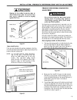
2. Align the photo eyes on the front side of the door.
(See Figure 50.)
3. Adjust the photo eyes on the rear side of the door
as required, dependent on the type of mounting
used by the installer.
NOTE: Pre-drilled mounting holes have been pro-
vided in the side columns to mount the
photoeyes. However, it is important to verify
with the customer what type of equipment
is moving through the door. Large
equipment may allow the photoeye beam
to shoot under the equipment causing the
door to close on the equipment. Different
mounting locations may be required.
ALUMINUM HOOD (OPTIONAL)
NOTE: The following procedure is required
only if your door was shipped with an
optional hood assembly.
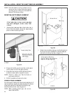
Self-Tapping
Sheet Metal
Screw
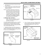
A7500047
Centerline of
Head Extrusion
and Center Cover
Figure 52
Center Cove
A door with a production width of up to 8 ft. 3 in. will have
a one-piece hood. A door with a production width
greater than 8 ft. 3 in. will have a three- or four-piece
hood. The installation procedure is the same for either
style of hood except where noted.
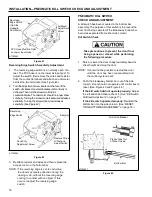
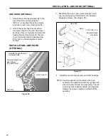
1. Attach the hood end covers to their respective U-
bracket installed earlier on the side columns. Use two
3/8-16 x 1 1/4-in. serrated-flange hex screws and nuts
for each end cover. (See Figure 51.)
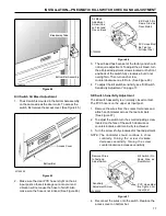
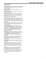
3. Three- or four-piece hood only: Install hood center
section(s) and secure to hood end sections using
#12 x 3/4-in. self-tapping sheet metal screws.
(See Figure 53.)
Self-Tapping
Sheet Metal
Screw
Head Extrusion
Serrated-Flange
Hex-Head Screw
(Two Each Side)
Serrated-Flange
Hex Nut (Two
Each Side)
End Cover
End Section Covers
(Mount on Top of
Center Section Cover)
A8500016
End Cover
Figure 51
Figure 53


