9
INSTALLATION—HEAD ASSEMBLY
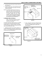
Figure 19
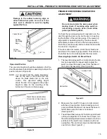
7. Bolt the flange bearing assembly to the side column using
two 1/2-13 x 1-1/4-in. serrated-flange hex screws and nuts
(or two 1/2-13 x 2-in. screws and nuts if spacers are
required, or nuts only if 6-in. screws were installed earlier).
DO NOT tighten the hex nuts at this time.
IMPORTANT: If the drum/fabric roll assembly
cannot be made level by adjusting the flange
bearing mounting bracket up or down, verify that
the side columns are plumb, square and level and
make any necessary adjustments.
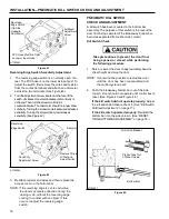
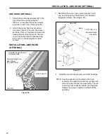
8. Place a carpenter’s level along the length of the
drum/fabric roll assembly and adjust the flange
bearing mounting bracket up or down, as required,
until the drum/fabric roll assembly is level.
Tighten the hardware securing the motor and the
flange bearing mounting brackets to the side
columns. Then tighten the set screw to lock the
flange bearing to the drum shaft. (See Figure 20
and Figure 21.
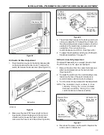
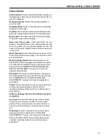
For a door with pullouts, verify that the two hex nuts
threaded on each 6-in. screw are tight against their
associated side column and mounting bracket.
Failure to tighten all eight nuts could result in
damage to the side columns. (See Figure 21.)
Figure 20
Figure 21
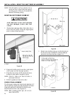
DO NOT remove the shipping bands holding the
fabric material to the drum roll assembly at this
time.
9. Do not remove the shipping bands securing the
fabric material to the drum roll. Only remove the
fasteners securing the drum assembly to the forklift.
Then lower and move the forklift out of the way.
IMPORTANT:
Install spacer between flange
bearing assembly and side column (if spacer
is supplied).
Serrated-Flange
Hex Screw
(Two Required)
Serrated-Flange
Hex Nut
(Two Required)
Flange
bearing
assembly
Head/Fabric
Roll assembly
Tighten Each
Set of Nuts on
6-in. Screws
Pullout
Mounting
Bracket
Side
Column
Tighten Hex Screws
(Tighten Hex Nuts If
Pullouts Are Used)
Tighten Flange
Bearing Set Screw
Adjust Bracket Up or
Down as Required
Level


