background image

10

START-UP

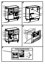
Turbine positioning (Fig. 3)

-  The machine must be positioned on a solid surface 
-  The turbine vents must be kept clean and unclogged (2).
-  Lock the brakes before each use (13).
- The exhaust (34) can be connected with the exterior (Ø 63

mm).

Power supply

- Turn the main switch (4) to “O” (off) before connecting this

appliance to the supply mains;

- supply mains voltage and frequency must match the

identification plate(18);

- connect to power socket outlets provided with earth

conductor and adequate protections.

Compressed air mains (To supply pneumatic tools)

- Do not exceed 6 bar;
- dehumidified and filtered air required;
- connect the appliance to the compressed air main with an

hose suitable for the air pressure and int. diam. 10 mm min.

Assembling the two-way link (29)

Insert the adaptor in the inlet nozzle (11).

Electrical tool connections

- Check for the tool switch turned off before connecting it to

the front panel socket outlet;

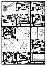
- insert the tool plug into the front panel socket (6) (pic. 7)

(AUTOMATIC plug only);

- connect the tool to the swivelling nozze with the hose

(pic. 9);

- do not plug electric tools exceeding the power indicated on

the front panel.

Pneumatic tool connections

- Check for the tool switch turned off before connecting it to

the front panel quick coupling;

-  connect the tool to the appliance with the quick couplings (7)

(pic. 6) and (8) (pic. 8);

- connect the coaxial hose (optional) to the quick coupling

(pic.6).

Check the tool functioning as indicated on their instructions
manual.

Preliminary checks

- Check that the dust collection bag (12) has been fitted in the

container (10); 

- check the dust container is correctly placed inside the unit

(fig. 11):

- check that the vacuum hose is properly fixed and does not

hinder tool movement;

- check that there are no leaks in the compressed air supply

system.

MACHINE USE

The machine can operates in manual or automatic mode: to
select the mode, turn the switch (4) to the right (automatic
mode) or to the left (manual mode) (pic. 4). 
The green indicator (5) turns on when the vacuum motor starts.

Using the machine in automatic mode (A)
Pneumatic connections and electric AUTOMATIC plug

Automatic operations means that the vacuum starts when an
electrical or pneumatic tool is turned on.
The vacuum will automatically turn off eight seconds after the
tool is turned off.

Electric SERVICE plug (15)

Electric SERVICE plug is supplied. When the tool connected to
the socket is turned on, the vacuum does not start.

Using the machine in manual mode (M)

Manual operations means that the vacuum runs continuously.
Power on the front panel outlet sockets is permanently active
during manual running.

MAINTENANCE

A yearly technical check on parts and filtering system by an
authorized service centre is required.

TURBINE ON indicator (pic. 4)

The green indicator turns on when the vacuum starts. 
Inside the electric control board a motor electric protection is
installed (27). 
When the TURBINE ON indicator turns on and the vacuum
motor is blocked, contact an Authorized Service Centre.

FILTER CHECK indicator (pic. 20)

A manual filter cleaning system is installed inside the unit.
When FILTER CHECK (25) indicator light turneds on, a manual
filter cleaning operation is required.

Manual filter cleaning system (pic. 5)

Follow the instruction on the filter cleaning label to correctly per-
morm a cleaning operation:
a) Turn the cleaner in manual mode (pic. 5A)
b) Close the suction (pic. 5B)
c) Wait 5 “ (pic. 5C)
d) Pull and release to clean (pic. 5D)
Repeat operations c and d 3 times
When the FILTER CHECK indicator light turneds off, the filter
efficiency condition is correct.

Ordinary check operations

For user servicing, the appliance must be dismantled, cleaned
and serviced, as far as it is reasonably practicable, without
causing risk to the maintenance staff and others. 
Suitable precautions include, decontamination before
dismantling, provision for local filtered exhaust ventilation where
the appliance is dismantled (according to local regulations),
cleaning of the maintenance area and suitable personal

Содержание KR2

Страница 1: ...TIEN ORIGINAL BEDIENUNGS UND WARTUNGSANLEITUNG INSTRUCCIONES ORIGINAL DE USO Y MANUTENCION AANWIJZINGEN VOOR HET GEBRUIK EN HET ONDERHOUD ORIGINEEL 1 ISTRUZIONI ORIGINALI PER L USO E LA MANUTENZIONE O...

Страница 2: ...2 5 2 1 3 4 5 30 22 30 14 3 31 32 11 6 7 13 2 17 23 2 15 21 33 1 28 16 18 22 20 27 4 24 25 5 23 26 9 19 10 12 12...

Страница 3: ...3 6 7 8 9 10 11 12 13 14 15 16 17 20 19 18 8 9 7 29 6 15 7...

Страница 4: ...da persone addestrate ed incaricate del suo utilizzo pertanto la macchina non destinata a essere usata da bambini o persone le cui capacit fisiche sensoriali o mentali siano ridotte l operatore deve e...

Страница 5: ...GLI SCOPI PREVISTI Questa macchina idonea a sollecitazioni elevate per applicazioni industriali secondo le norme EN60335 1 e EN60335 2 69 utilizzare la presa di corrente della macchina solo per gli sc...

Страница 6: ...u funzionare in modalit automatico o manuale selezionare la modalit prescelta ruotando l interruttore 4 o verso destra automatico o verso sinistra manuale fig 4 la spia verde 5 si accende all avvio de...

Страница 7: ...ato Avaria del sensore pneumatico Rivolgersi ad un Centro Assistenza autorizzato Utensile elettrico collegato a presa SERVICE Collegare utensile elettrico a presa AUTOMATIC La capacit di aspirazione i...

Страница 8: ...e can only be operated by trained people in charge machine not intended to be operated by kids or mental sensorial defective people before use users should be provided with information instruction and...

Страница 9: ...d industrial operations in accordante with EN60335 1 e EN60335 2 69 the front power socket is only intended for specific use as indicated in the present instruction manual VERSION L Appliance suitable...

Страница 10: ...ight automatic mode or to the left manual mode pic 4 The green indicator 5 turns on when the vacuum motor starts Using the machine in automatic mode A Pneumatic connections and electric AUTOMATIC plug...

Страница 11: ...Contact an authorised service centre Pneumatic valve fault Contact an authorised service centre Electric tool connected to SERVICE plug Connect electric tool to AUTOMATIC plug Vacuum flow is insuffic...

Страница 12: ...rteilen herausnehmen berpr fung des Verpackungsinhalts Die Verpackung enth lt die mit einem Stromkabel ausger stete Maschine 1 langen Ansaugschlauch 3 Staubbeutel 12 1 Zwei Wege Verbindung 29 Folgende...

Страница 13: ...AZARD 1mg m VERSION M Klassifiziert in der Staubklasse M f r gef hrdende Schleifst ube der Grenzwerte Klasse M medium HAZARD 0 1mg m Bezogen auf alle Regelungen bez glich der Schadstoffe und Substanze...

Страница 14: ...nuellem oder automatischen Modus betrieben werden F r die Auswahl des Modus drehen Sie den Schalter 4 in die rechte Position Automatik Modus oder in die linke Position Manuell Modus Bild 4 Die gr ne K...

Страница 15: ...t tigung des Hakens Abb 12 13 aus der Einheit Schrauben Sie den unteren Befestigungsknopf des Filters los und entfernen Sie die Dichtung Abb 19 Entfernen Sie den gebrauchten Filter und bringen Sie ihn...

Страница 16: ...devono corrispondere ai dati indicati sulla targhetta di identificazione 1 Prima di collegare la spina accertarsi che l utensile sia spento MONTAGGIO DELL UTENSILE LH16ENS LH18ENS Posizionare la calo...

Страница 17: ...errupteur 4 soit sur la position 0 teint la tension et la fr quence du secteur doivent correspondre aux donn es indiqu es sur la plaque d identification 18 ne brancher qu des prises quip es de mise la...

Страница 18: ...ne de fa on continue Sur la prise de la machi ne la tension lectrique est n anmoins disponible ENTRETIEN Le fabricant ou le personnel autoris doit effectuer au moins une fois par an une v rification t...

Страница 19: ...fixer avec le crochet fig 11 fermer la porte Utiliser exclusivement les pi ces de rechange RUPES Pour toute information sur les codes des pi ces de rechange et les Centres d Assistance agr s consulte...

Страница 20: ...en Elektromagnetische Vertr glichkeit EN 55014 1 2006 A1 2009 A 2 2011 CISPR 14 1 2005 EN 55014 2 1997 A1 2001 A2 2008 EN 50366 2003 A1 2006 EN 61000 3 2 2006 A1 2009 A2 2009 EN 61000 3 3 2008 Elektro...

Страница 21: ...RUPES S p A Via Marconi 3A 20080 VERMEZZO Mi Italy Tel 02 946941 Fax 02 94941040 Uff Vendite e assistenza clienti Tel 39 02 94694312 e mail info_rupes rupes it web www rupes com CRev 0 09 2014...

Отзывы: