


RDLC320 Controller User Manual
12
/
45
© 2016 Ruida Technology. All Rights Reserved.
X/Y-axle spacing interface CN4 (6Pin, 3.81mm space)
No.
Symbols
Definitions
1
OGND
External power ground (output)
2
LmtY-
The spacing from axle Y- and Y to 0 coordinate
3
LmtY+
The spacing from axle Y+ and Y to max. coordinate
4
LmtX-
The spacing from axle X- and X to 0 coordinate
5
LmtX+
The spacing from axle X+ and X to max. coordinate
6
O 5V
External power 5V (output)
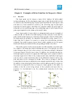
The spacing polarity is optional, that is to say, when the motion axle reaches the
spacing position, it will trigger a low-level signal so as to make the corresponding
LED (under the cover) light; when the motion axle leaves the spacing position, it will
trigger a high-level signal or disconnect the spacing signal so as to make the spacing
indicator go out, but when it leaves the spacing, the corresponding indicator will light
and the spacing polarity become positive. The mistaken setting of spacing polarity
will result that the spacing can’t be detected when the system is reset so as to lead to
the collision of axles.
4.5
X/Y/Z-axle Motion Drive Interface
The interfaces of the above three motion axles are the same (6Pin, 3.81mm space).
The Axle-X interface is exampled.
Pin Symbols
Definitions
1
GND
Kernel power ground (output, only used for common
cathode connection of driver)
2
xDir+
Differential plus end of directional signal
3
xDir-
Differential minus end of directional signal
4
xPulse-
Differential minus end of pulse signal (when the common
anode connection is used and the pulse rising edge valid,
input will start from this pin.)
5
Differential plus end of pulse signal (when the common
anode connection is used and the pulse falling edge valid,
input will start from this pin.)
6
+5V
Kernel 5V power positive (output, only used for common
anode connection of driver)
The polarity of directional signal for driver pulse signal can be set. Where a
certain axle is reset, it will move to the opposite direction of machine origin, which
means the polarity of directional signal for this axle is not correct. In such a case, the
connection between this axle and the motor driver can be broken first (otherwise the
controller cannot be detected to the spacing so as to lead to the collision of this axle),