background image

6

English


Tel. +49 7930 9211-0               Fax +49 7930 9211-150

Any use of the product other than described in chapter “Intended use” is considered as improper.

The following points are improper and dangerous:

• 

Delivery of explosive and flammable media or operation in potentially explosive atmospheres.

• 

Delivery of aggressive and abrasive media.

• 

Delivery of media containing dust or grease.

• 

Installation outside without any protection against the weather.

• 

Installation in wet areas.

• 

Operation without the duct system.

• 

Operation with closed air connections.

2.2. Improper use

Assembly, commissioning,operation, disassembly and service (including maintenance and repair) 

require basic mechanical and electrical knowledge, as well as knowledge of the appropriate tech-

nical  terms.  In  order  to  ensure  operating  safety,  these  activities  may  therefore  only  be  carried 

out by qualified technical personnel or a person under the direction and supervision of qualified 

personnel. Qualified personnel are those who can recognize possible hazards and institute the 

appropriate  safety  measures  due  to  their  professional  training,  knowledge,  and  experience,  as 

well as their understanding of the relevant conditions pertaining to the work to be done. Qualified 

personnel must observe the rules relevant to the subject area.

2.3. Personnel qualifications

In this manual, there are safety instructions before the steps whenever there is a danger of per

-

sonal injury or damage to the equipment. The measures described to avoid these hazards must 

be observed.

2.4. Safety instructions in this manual

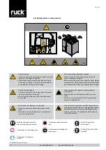
Safety instructions are set out as follows:

Safety sign (warning triangle)


  - Draws attention to the risk.

• 

Type of risk!


  - Identifies the type or source of the hazard.

» Consequences


 - Describes what occurs when the safety instructions are not complied with.

→  Precautions 


  - States how the hazard can be avoided.

General warning!

Indicates possible hazardous situations. Failure to observe the warn-

ings may result in personal injury and / or damage to property.

Electricity warning (hazardous voltage)!

Indicates possible hazards due to electricity. Failure to observe the warn

-

ings may result in death, injury and/or damage to property.

Hot surface warning!

Indicates possible hazards due to high surface temperatures. Failure 

to observe the warnings may result in personal injury and/or damage to 
property.

Crushing of fingers warning!

Indicates possible hazards due to moving and rotating parts. Failure to 

observe the warnings may result in personal injury.

Overhead load warning!

Indicates possible hazards due to overhead loads. Failure to observe the 

warnings may result in death, injury and/or damage to property.

Important instructions follow!

Instructions for safe, optimum use of the product.

Safety sign 

(warning 

triangle)

Consequence

Содержание ROTO K 1050 V WOJL

Страница 1: ...0 FC RLI 1200 FC RLI 1600 FC RLI 2000 FC RLI 700 EC RLI 1200 EC RLI 1600 EC RLI 2000 EC ROTO KOMPAKT ROTO K 1050 V WOJL ROTO K 1700 V WOJL ROTO K 2800 V WOJL ROTO K 4200 V WOJL Assembly and Operating...

Страница 2: ...g a certain condition or suitability for a cer tain application can be derived from our information The informa tion given does not release the user from the obligation of own judgment and verificatio...

Страница 3: ...installation positions 12 6 2 Duct connections 12 6 3 Application limits 12 6 4 Medium connections Heating Coil 12 7 Electrical connection 13 7 1 Overcurrent protection 14 7 2 Description external in...

Страница 4: ...el heat exchanger 38 10 3 2 Belt drive for rotating wheel 38 10 3 3 Air filter 39 10 3 4 Changing the battery 40 11 Modbus communication interface 41 11 1 Wiring diagram 41 11 2 Interface information...

Страница 5: ...operating instructions when you pass the product on to third parties 1 1 Rules and regulations 1 2 Guarantee and liability Also observe the generally applicable legal or otherwise binding regulations...

Страница 6: ...a 2 3 Personnel qualifications In this manual there are safety instructions before the steps whenever there is a danger of per sonal injury or damage to the equipment The measures described to avoid t...

Страница 7: ...r removed Make sure that all electrical connections are either used or covered Commission the product only if it is installed completely The power switch must be always fully functional and easy acces...

Страница 8: ...or moving parts Failure to observe the hazard may lead to serious injury Work may only be performed once the impeller has come to a complete halt Never clean the internal space with flowing water or...

Страница 9: ...internal and external walls The hous ing is insulated with 40 mm mineral wool The unit can be operated at a constant volume Control using external sensors provides the appropriate ventilation Data in...

Страница 10: ...Model ROTO K V Fig 2 Typ ROTO K V Legend 15 Heating coil Heater 16 Frost protection controller 17 Supply air temperature sensor 18 Controller board 19 Safety labels 20 Cover for terminal box 21 Termi...

Страница 11: ...perating manual and the regulations and standards in force The following points should be noted and followed The foundation must be even and levelled It must not exhibit unevenness or a slope in any d...

Страница 12: ...e the freezing point of the water The only advantage of the bypass circuit over the admixture circuit arises when the pipe lengths between three way ball valve and water heater are very long Because t...

Страница 13: ...between the unit and the duct system Check all protective measures after the electrical connection work earthing resistance etc Connection compartment Connections on the unit The connection compartme...

Страница 14: ...ing diagram An external voltage must never be applied to this connection The control system would be destroyed Any devices providing a potential free contact e g central building control system can be...

Страница 15: ...contact is closed Electrical connec tion with Vmax 230 VAC and Imax 2 A There is no double insulation from the mains Is the set value reached or the supply air temperature sinks below 16 C the contac...

Страница 16: ...from the electricity supply and make sure that it cannot be switched back on again Never reach into the impeller or other rotating or moving parts Failure to observe the hazard may lead to serious in...

Страница 17: ...u points and make changes to your unit settings and values A Control unit B Display Operating display 1 ON OFF selection 2 Setpoint temperature 3 Fan steps 4 Settings 5 Display current time C Control...

Страница 18: ...selection buttons and can increase or reduce the setpoint value at the control unit The setting range is limited by parameters P 1 and P 2 Change fan step Fan step 2 is preset at first commissioning...

Страница 19: ...ws the selection menu By touching the desired icon you can change between the parameters you need By selecting OK you confirm the chosen language The display switches into operating display 9 5 1 Lang...

Страница 20: ...ettings icon The selection menu will then appear on the display Temperatures Display of the currently prevailing air temperatures in the device ODA Outside air temperature SUP Supply air temperature E...

Страница 21: ...cted The individual inputs can be queried with the selection tools and The selection is made from right to left Description 1 true 0 false Position Consequence Description 1 unimplemented UNUSED 2 uni...

Страница 22: ...K S Variable control with constant volume operation When confirming constant air volume control the following parameters have to be adjusted checked P 14 without external sensor Constant air volume c...

Страница 23: ...and P28 P 15 Minimum ventilation supply air P 16 Minimum ventilation extract air The volumetric flow can also be adjusted to MINIMUM VENTILATION night setback This param eter is controlled using the t...

Страница 24: ...gs can be found in the measuring range of the used measuring transducer The measur ing range is already preset for devices with integrated CO2 sensor Example Measuring area sensor 0 5000 ppm P 23 0 P...

Страница 25: ...ontrolled by external measuring transducer VOC Sensor type VOC P 23 and P 24 These settings can be found in the measuring range of the used measuring transducer The measur ing range is already preset...

Страница 26: ...211 0 Fax 49 7930 9211 150 SENSORTYPE W O EXT SENSOR Factory setting SENSORTYPE W O EXT SENSOR SENSORTYPE SENSORTYPE EXT CTRL SENSORTYPE SENSORTYPE EXT CTRL Continued on page 29 P 14 External control...

Страница 27: ...s param eter is controlled using the timer switch and can be set across the entire allowed pressure range P 17 Basic ventilation supply air P 18 Basic ventilation extract air The required duct pressur...

Страница 28: ...s The device automatically balances the air volume when sections will be added on or switched off The desired supply pressure must only be set on the control unit A response of the air volume controll...

Страница 29: ...r compares the air temperature measured at the temperature sensors with the reference temperature set on the control unit In the case of heating a difference between the set point and actual temperatu...

Страница 30: ...order to execute the filter calibration By touching the icon the unit switches to the calibration mode Display flashes CALIBRATE FILTER P 25 Supply air filter pressure loss Setting for pressure loss...

Страница 31: ...operation The unit can only be switched on if the contact is closed If the contact is open the display will show NOT ENABLE The contact has to be closed and at the end confirmed by selecting OK The d...

Страница 32: ...increases the control becomes more sensitive CAUTION Due to highly sensitive settings the control tends to pulsate P 6 Temperature correction The room temperature sensor within the control unit may sh...

Страница 33: ...Setting the current time day You can switch from the Operating display to the Selection menu through the Settings icon Here you have the possibility to set the current time and weekday by pressing Se...

Страница 34: ...the last item is confirmed for row 3 the display switched to day 2 Tuesday for which you can also set the ON and OFF switching times of the unit Days 3 to 7 then follow After you have set all the par...

Страница 35: ...the hours and minutes is done the same way with and and with You may now set a second period of time for day 1 Monday in row 2 Proceed the same way as you did for row 1 If you do not wish to set a sec...

Страница 36: ...3 0 00 0 00 English Tel 49 7930 9211 0 Fax 49 7930 9211 150 Basic ventilation Basic ventilation Basic ventilation Minimum ventilation Day 1 Day 1 Day 1 Fig 16 Systematic drawing without timer settings...

Страница 37: ...chieved after 20 min an error message is displayed Afterwards the unit turns itself completely off until the fault is repaired see 14 2 Error table F07 9 10 2 Hot water coil The unit series can be equ...

Страница 38: ...sion There must not be any faults or wear on the motor s pulley The pulley must be parallel to the circulating heating coil and must not twist 10 3 2 Belt drive for rotating wheel Rotating wheel heat...

Страница 39: ...ensor this can be seen on the status display The filter must be changed when the level of clogging reaches 100 To reset the filter display after changing the filter press buttons A and at the same tim...

Страница 40: ...y shows COMPLETED The contamination display is set back to 0 after calibration mode The filter change counter will then increase by one Calibrate filter Status display 10 3 4 Changing the battery Stat...

Страница 41: ...ption 08 Hex Return Query Dat 00 Send the received message back 08 Hex Restart Communications 01 Restart communication 08 Hex Force Listen Only Mode 04 Switch to listen only mode Fig 25 Control unit 1...

Страница 42: ...sic ventilation supply air See Table below or 50 500 Pa integer R W 40019 18 Basic ventilation extract air See Table below or 50 500 Pa integer R W 40020 19 Intermittent ventilation supply air See Tab...

Страница 43: ...Reserved R W Bit 12 Reserved R W Bit 13 Reserved R W Bit 14 Reserved R W Bit 15 Reserved R W Register address Parameter name Value range ROTO K 1050 V ROTO K 1700 V ROTO K 2800 V ROTO K 4200 V ROTO K...

Страница 44: ...er R 30007 6 Pressure difference filter 1 0 1000 Pa integer R 30008 7 Pressure difference filter 2 0 1000 Pa integer R 30009 8 Soiling indicator 1 0 100 integer R 30010 9 Soiling indicator 2 0 100 int...

Страница 45: ...Damper position 7 Frost protection triggered 8 Safety thermostat triggered 9 Thermal switch for ventilator triggered 10 Error fan 11 Reserved 12 Not enabled 13 Cooling plant defective 14 Fire detector...

Страница 46: ...1 Have the unit s operating conditions or operating range been changed 2 Have any changes e g reconfigurations or repairs been performed on the overall system installation electrics control or to the...

Страница 47: ...xtracted air temperature sensor is defective or the cable is broken Replace the defective temperature sensor or replace the broken cable if necessary After the failure reason is remedied the failure m...

Страница 48: ...ch the unit off check wiring and fans and if needed replace damaged fan After the failure reason is remedied the failure must be confirmed with OK Error in rotor motor Error message to the control of...

Страница 49: ...th W mm 816 954 1153 1409 Height H mm 1099 1253 1610 1903 Nominal width NW mm 600 x 250 600 x 250 250 x 850 1100 x 350 Weight kg 146 248 362 552 Operating voltage V 400V 3 N 400V 3 N 400V 3 N 400V 3 N...

Страница 50: ...component 5 20 10 P 6 Temp correction of the ambient temp sensor on the control unit 5 C 5 C 0 P 7 Address 1 247 1 P 8 Baud rate 2400 4800 9600 14400 19200 9600 P 9 Fan calibration supply air 800 1200...

Страница 51: ...xtract Air Fortluft Exhaust Air Aussenluft Fresh Air 1150 998 1099 209 5 225 386 33 2x3 4 Innengewinde 816 500 523 220 197 72 197 72 197 72 53 2 16xM8 Einietmuter 1517 816 ROTO K 1050 V English 16 2 T...

Страница 52: ...52 1399 1121 1150 143315 142269 669 315 819 8 English Tel 49 7930 9211 0 Fax 49 7930 9211 150 ROTO K 1050 V Transition 315...

Страница 53: ...Air Abluft Extract Air Fortluft Exhaust Air Aussenluft Fresh Air 1375 1161 1253 291 5 33 492 222 3 2x3 4 Gewinde 1694 891 891 600 250 76 250 76 250 76 273 53 5 623 16 x M8 Einietmuter ROTO K 1700 V En...

Страница 54: ...54 1595 1375 1553 1253 791 400 1378 143324 143321 140188 English Tel 49 7930 9211 0 Fax 49 7930 9211 150 ROTO K 1700 V Transition 400...

Страница 55: ...5 557 8 221 4 2 x 3 4 Gewinde 45 6 250 850 1092 280 880 110 118 110 250 16 x M8 Einietmuter Abluft Extract Air Aussenluft Fresh Air Fortluft Exhaust Air Zuluft Supply Air 1092 1948 Offene T re ROTO K...

Страница 56: ...56 1603 4 1812 1495 145539 145540 139032 English Tel 49 7930 9211 0 Fax 49 7930 9211 150 ROTO K 2800 V MAK Motor shut off flap...

Страница 57: ...Abluft Extract Air Fortluft Exhaust Air Aussenluft Fresh Air 1800 1811 1903 518 223 659 33 2x3 4 Innengewinde 1355 5 2351 1355 5 1099 349 91 349 91 349 91 380 53 5 1130 16xM8 Einietmuter ROTO K 4200 V...

Страница 58: ...58 1903 2112 1803 1360 145594 145596 141531 English Tel 49 7930 9211 0 Fax 49 7930 9211 150 ROTO K 4200 V MAK Motor shut off flap...

Страница 59: ...1 L1 L1 L1 Einspeisung Power input 400V 3 N 50Hz Sicherung extern max 10A Fuse external max 10A Zuluftventilator 2 Supply air fan 2 Hauptschalter Main switch bk ye bk ye B1 Volumenstrom Zuluft Supply...

Страница 60: ...L1 L1 Einspeisung Power input 400V 3 N 50Hz Sicherung extern max 10A Fuse external max 10A Abluftventilator 2 Extract air fan 2 Hauptschalter Main switch bk ye bk ye B1 Volumenstrom Zuluft Supply air...

Страница 61: ...00V 3 N 50Hz Sicherung extern max 16A Fuse external max 16A Zuluftventilator Supply air fan Hauptschalter Main switch wh bu ye bu ye wh St rung Fault St rung Fault wh wh B1 Volumenstrom Zuluft Supply...

Страница 62: ...n max 16A Fuse external max 16A Zuluftventilator Supply air fan Abluftventilator Extract air fan Hauptschalter Main switch wh bu ye bu ye wh St rung Fault St rung Fault wh wh B1 Volumenstrom Zuluft Su...

Страница 63: ...icherung extern max 16A Fuse external max 16A Zuluftventilator Supply air fan Abluftventilator Extract air fan Hauptschalter Main switch wh bu ye bu ye wh St rung Fault St rung Fault wh wh B1 Volumens...

Страница 64: ...A Out 0V 0V 24V D In A Out A Out 24V D In 24V 24V 24V 24V 24V 24V 24V D In D In D In D In D In D In Temp 1 Temp 2 Temp 3 Temp 4 L1 L1 L1 L1 B1 Volumenstrom Zuluft Supply air flow B2 Volumenstrom Abluf...

Страница 65: ...nluft Fresh air Abluft Extract air Zuluft Supply air Bedienger t Remote control Optional manuelle Verbindung mit einem Kabel manuell connection with a cable 120Ohm 3 Wege Ventil 3 way valve K hlen Opt...

Страница 66: ...A B 24V 1 X14 2 3 4 5 6 7 8 9 10 11 12 13 1 X9 2 3 4 5 6 7 8 9 N X3 2 3 N 5 6 N 8 9 1 X6 2 3 N 5 6 N 8 9 1 X16 2 N 4 5 6 7 8 9 N X4 N N 4 5 6 7 8 9 L1 L11L2 L21L3 L31 N N N PE PE PE PE 15 30 V 0V 0 10...

Страница 67: ...XB1 XB3 F1 F2 0V 0V 0V 0V 0V L1 L1 L1 L1 L1 L1 L1 L1 A In A In A In A Out A Out 0V 0V 24V D In A Out A Out 24V D In 24V 24V 24V 24V 24V 24V 24V D In D In D In D In D In D In Temp 1 Temp 2 Temp 3 Temp...

Страница 68: ...ents concerning a certain condition or suitability for a certain application can be derived from our information The information given does not release the user from the obligation of own judgment and...

Отзывы: