32
9:51
9:51
9:51
9:51
9:51
9:51
9:51
9:51
0% 4%
21,0°C
P 4
10
P 5
10
P 6
0,0°
P 7
1
P 8
9600
P 9
0,960
P10
0,930
English
Tel. +49 7930 9211-0 Fax +49 7930 9211-150
I-COMPONENT
P-COMPONENT
TEMP.ADJUSTME
ADDRESS
BAUD RATE
SUPPLY AIR
FAN BALANCE
EXTRACT AIR
FAN BALANCE
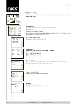
P 4 I - component
A value between 5-20 can be set for the I – component.
The factory setting is at 10.
If the value decreases, the control becomes more sensitive.
CAUTION! Due to highly sensitive settings, the control tends to pulsate.
P 5 P - component
A value between 5-20 can be set for the P – component.
The factory setting is at 10.
If the value increases, the control becomes more sensitive.
CAUTION! Due to highly sensitive settings, the control tends to pulsate.
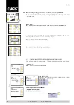
P 6 Temperature correction
The room temperature sensor within the control unit may show some deviation from the actual room
temperature. In this case, the control sensor can be corrected in the range from -5 °C to 5 °C.
P 7 Address
The bus address can be set between 1 and 247 with parameter P27 on the control unit.
Every unit with a Bus connection has to have an individual address.
Make sure that an address is not used for two devices. This can lead to malfunctions of the complete
bus system.
P 8 Baud rate
The baud rate defines the data speed.
2400, 4800, 9600, 14400 and 19200 baud rates can be set.
1 stop bit (fixed), no parity
P 9 Fan calibration supply air
P 10 Fan calibration extract air


