background image


Date:


09-May-2019


Product name 

RTX2018 

File

: RTX2018 User Manual 1.0.docx 

Ref.:  FHA


Page: 26 of 34 


This  document  and  the  information  contained  is  property  of  RTX  A/S,  Denmark,  and  should  be  regarded  as  confidential.


Unauthorized copying is not allowed. The information in this document is believed to be correct at the time of writing. RTX A/S 
reserves the right at any time to change said content, circuitry and specifications. 

5.4.1

  DUT Control for TX Measurements 

The 

DUT Interface

 and 

“DUT C

ontrol

” fields

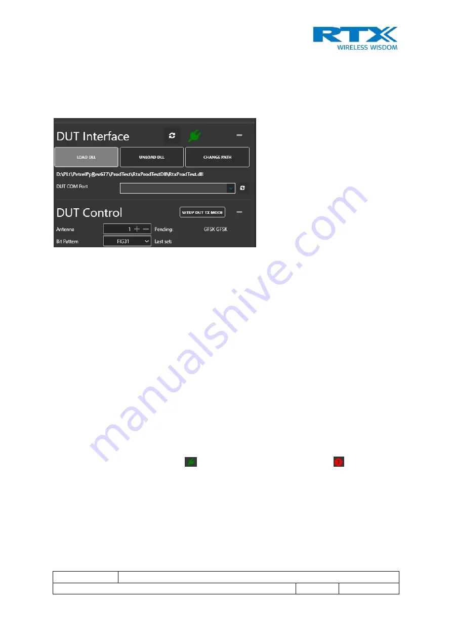
 (see Figure 15 below) in the lower left-hand 

corner of the window can be used to control the DUT. This will only work when the DUT is 
running with an RTX-supplied firmware 

(

Note 1

)

.  


Figure 15. DUT interface TX 

Communication with the DUT is done via a product-specific 

“RtxProdTest.DLL”

. To load this 

DLL, 

press “Load DLL”. 

The previously loaded DLL will be loaded. If none has been selected, a 

‘Open file menu’ 

will appear and the desired DLL can be selected.  

 
The 

“DUT COM Port” field is 

a drop-down menu for selection of the COM port to be used for 

communication. The drop-down menu will be populated at program launch and whenever the 

Refresh

 button is pressed next to it.  

 
A new DLL can be selected and opened at any time 

using the “Change Path” button. 


Pressing the “Unload DLL” will unload the DLL and 

disallow any DUT communications. This will 

gray out

” (disable)

 the DUT control in the TX tabs and the BER measurement buttons in the 

RX field as these are now longer functional.  
 
There  is  a  refresh  button  t

o  the  right  of  the  “DUT  Interface”  field 

that  will  check  the 

communication with the DUT using the “IsTargetConnected()” c

all. 

 
If the connection is ok, a green icon 

 appears, if not, an exclamation mark 

 will be shown.  


There is a “Setup DUT in Tx Mode” button i

n the 

DUT Control

 area. Pressing this button will 

send a “SetAdvancedBurstMode” test

 command to the DUT. 


As this command holds a large number of parameters, the GUI itself will determine the correct 
values for the command.  
 
The command will make the DUT send DECT full slot frames with the: 
 

Содержание RTX2018

Страница 1: ...on contained is property of RTX A S Denmark and should be regarded as confidential Unauthorized copying is not allowed The information in this document is believed to be correct at the time of writing...

Страница 2: ...warranted against defects in material and workmanship for a period of one year from date of shipment During the warranty period RTX will at its option either repair or replace products which prove to...

Страница 3: ...information in this document is believed to be correct at the time of writing RTX reserves the right at any time to change said content circuitry and specifications The general safety precautions acc...

Страница 4: ...RTX2018 Interface Specification provides programming guidance for users of the RTX2018 who would like to develop a test application software The document includes a programming reference along with a...

Страница 5: ...Application Programming Interface ARB Arbitrary ATE Automatic Test Equipment BER Bit Error Rate COM Communication DECT Digitally Enhanced Cordless Telecommunications DLL Dynamic Link Library DNS Doma...

Страница 6: ...llation 10 3 1 System Overview 10 3 2 Driver Installation 10 3 3 Waveform Installation 10 4 RTX2018 Installation 11 4 1 RTX2018 DLL 12 4 2 Documentation 13 5 RTX2018 User Manual 14 5 1 General GUI Des...

Страница 7: ...4 Figure 5 Tester configuration 15 Figure 6 RX measurement tab 17 Figure 7 RX tab in manual DUT mode 18 Figure 8 RX setup details 19 Figure 9 RX measurement detail 20 Figure 10 TX GFSK measurement tab...

Страница 8: ...s the right at any time to change said content circuitry and specifications 1 Introduction This document describes the installation setup and use of the RTX2018 test platform consisting of a Rohde Sch...

Страница 9: ...stallation Requirements 2 1 RTX2018 To ensure that the user has the latest software and documentation for the RTX2018 prior to installation it is recommended to visit the RTX Download Center https www...

Страница 10: ...se the connection is the Localhost or IP address 127 0 0 1 3 2 Driver Installation The CMW100 driver needs to be installed on the server PC to which the CMW100 is connected via USB Please refer to 2 f...

Страница 11: ...e RTX2018 firmware and DLL is installed with the file RTX2018Setup exe When this program is launched the first dialog box shows a selection option for the installation folder for the RTX2018 see Figur...

Страница 12: ...r 1201 0002k03 106863 LicenseCode 0563467856cd1b4306ffa5ad8ee2b938 ExpireDate 31 03 2019 c This license file allows the DLL to operate with the specific CMW100 HW and related serial number s as shown...

Страница 13: ...reserves the right at any time to change said content circuitry and specifications This is the DLL that interacts with the CMW100 driver and performs the measurement calculations Please refer to 1 for...

Страница 14: ...the time of writing RTX A S reserves the right at any time to change said content circuitry and specifications 5 RTX2018 User Manual The GUI Graphical User Interface is an application on top of the RT...

Страница 15: ...it is necessary to establish the connection between the PC running the RTX2018 GUI DLL and the PC that has the USB connection to the CMW100 HW The address of the CMW100 PC can be entered in the Server...

Страница 16: ...box The channel frequency is selected simultaneously for both RX and TX 5 1 3 Slot Types The Slot Type field drop down menu is used to select between predefined slot types The slot types are used to...

Страница 17: ...ing the ETSI specified RF loopback connection as is the case for e g the RTX2012 DECT RF tester The RTX2018 uses the Non signalling mode which means that there is no RF connection established between...

Страница 18: ...mode is control of the signal that is transmitted by the CMW100 RF generator The DUT control area and the Measurement area will be disabled The BER FER in this case will need to be read out from the...

Страница 19: ...or Disable the RF generator The RF output level controlled either by entering a numeric value in the Level box or by the by slider below The range is from 100 to 10 dBm The Cable Loss is considered b...

Страница 20: ...he DUT If this is successful a green connected icon appears if not a red icon appears 5 2 6 BER FER Measurements The idea behind the BER FER measurement is that the RF generator transmits a known fixe...

Страница 21: ...he DUT which can be o Idle no measurement has been initiated o Searching the DUT is searching to obtain time synchronization o Adjusting Frequency the DUT is adjusting crystal frequency to be fully sy...

Страница 22: ...n the next section 5 3 1 TX Measurement Setup The Expected Power is a configuration value for the CMW100 The Expected Power should be set close to the measured TX power The dynamic range of the CMW100...

Страница 23: ...trigger level A good value would be approx 30 to 20 dB relative to the Expected Power Please note that if the Expected Power is much higher than the real TX power level and the Trigger Offset value is...

Страница 24: ...r button The shorter the capture length the smaller the amount of data transferred to the DLL which also will decrease the computation time The allowed range for the start of capture time is 50 to 11...

Страница 25: ...Search field can be enabled with the small slider In this case the analysis program will search for a sync word within the capture signal The sync word is selected from a dropdown menu Two sync words...

Страница 26: ...and the desired DLL can be selected The DUT COM Port field is a drop down menu for selection of the COM port to be used for communication The drop down menu will be populated at program launch and whe...

Страница 27: ...elected in the Bit Pattern box 5 5 TX GFSK Measurement Results The measurement results for the GFSK are shown in Figure 166 below Figure 16 TX GFSK results After the setup has been completed the measu...

Страница 28: ...burst The RTX2018 will also show the results graphically as shown in Error Reference source not found and Figure 18 below Error Reference source not found below shows the result as it looks without b0...

Страница 29: ...s the right at any time to change said content circuitry and specifications Figure 18 TX GFSK graphical results b0 search enabled 5 6 TX PSK Measurement Results The TX PSK tab is used to perform measu...

Страница 30: ...at any time to change said content circuitry and specifications Freq Offset shows the frequency offset measured in kHz of the signal The offset is estimated on the demodulated signal RMS EVM shows the...

Страница 31: ...X graphical PI2 DBPSK results no b0 search The upper window IQ Data shows the constellation diagram of the received signal The brown circles show the locations of reference points for the modulation T...

Страница 32: ...and should be regarded as confidential Unauthorized copying is not allowed The information in this document is believed to be correct at the time of writing RTX A S reserves the right at any time to...

Страница 33: ...and should be regarded as confidential Unauthorized copying is not allowed The information in this document is believed to be correct at the time of writing RTX A S reserves the right at any time to c...

Страница 34: ...ll coding examples to aid the user in integrating the RTX2018 into an automatic application The RTX2018 DLL CmwIntf dll is the Dynamic Link Library file which provides API for remote control of the in...

Отзывы: