RRS Jade XRD-01RDHAM3 Series Скачать руководство пользователя страница 6

6

AD JUST MENT  METHOD

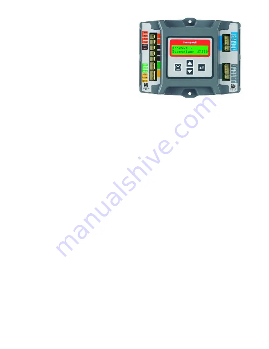
The user interface consists of an LCD display and a
4-button keypad on the front of the Economizer module.
The LCD is a 16 character by 2 line dot matrix display.

Power Up Cycle

All setpoints and advanced settings are restored after any
power loss (a power loss is assumed if voltage falls below
18 Vac). Normal operation is restored when power returns
above 18 Vac.

Ini tial Menu Dis play

On initial startup, 

Honeywell 

displays on the first line and

Economizer W7220

 on the second line. After a brief

pause, the revision of the software appears on the first line
(second line is blank). It then displays 

W7220


 o

n the first

line and STATUS on the second line.

Key pad

The four navigation buttons illustrated in 

Figure 9

 are used 

to scroll through the menus and menu items, select menu
items, and to change parameter and configuration
settings.

Us ing the Key pad with Menus

To use the keypad when working with menus:

l

Press the


p

 button to move to the previous menu.

l

Press the 

q

 button to move to the next menu.

l

Press the 

8

  button (Enter) to display the first item in

the currently displayed menu.

l

Press the 

Ó


button (Menu up) to exit a menu’s item

and return to the list of menus.

Us ing the Key pad with Set tings and Pa ram e ters

To use the keypad when working with Setpoints, System
and Advanced Settings, Checkout tests, and Alarms:

l

Navigate to the desired menu.

l

Press the 

8


button (Enter) to display the first item in

the currently displayed menu.

l

Use the 

p

 and 

q

 buttons to scroll to the desired

parameter.

l

Press the 

8

  button (Enter) to display the value of the

currently displayed item.

l

Press the 

p

  button to increase (change) the

displayed parameter value.

a

l

Press the 

q

  button to decrease (change) the

displayed parameter value.

a

l

Press the 

8

  button to accept the displayed value and

store it in non-volatile RAM.

l

When the value is accepted,  

CHANGE STORED

 is

displayed on the LCD.

l

Press the


8

  button (Enter) to return to the current

menu parameter.

l

Press the 

Ó

 button (MenuUp/Exit) to return to the

previous menu.

Time-out and Screensaver

When no buttons have been pressed for 10 minutes, the
LCD displays a screen saver, which cycles through the
Status items. Each Status items displays in turn and cycles 
to the next item after 5 seconds.

SETUP  AND  CON FIG U RA TION

Before being placed into service, the JADE™ Economizer
module must be setup and configured for the installed
system. Use the System Setup menu, the Advanced Setup 
menu (if necessary), and the Setpoints menu to
accomplish this.

Menu Struc ture

The following tables illustrate the complete hierarchy of
menus and parameters for the JADE™ Economizer
system.

The Menus in display order are:

l

STATUS

l

SETPOINTS

l

SYSTEM SETUP

l

ADVANCED SETUP

l

CHECKOUT

l

ALARMS

IMPORTANT

Your menu parameters may be different depending on
your configuration. For example if you do not have a DCV
(CO

2

) sensor, then none of the DCV parameters appear.

a

 When val ues are dis played, press ing and hold ing the 

p

 or 

but ton

causes  the  dis play  to  au to mat i cally  in cre ment.

FIGURE 9

Содержание Jade XRD-01RDHAM3 Series

Страница 1: ...REQUIRED FOR INSTALLATION 3 8 electric drill with 5 16 socket Waterproof exterior duct sealant Sheet metal tools e g shears PACKAGE CONTENTS XRD 01RDHAM3 economizer with controller actuator and outsid...

Страница 2: ...ng economizer insertion STEP 5 Remove jumper plug and slide economizer into unit return air section SEE FIGURE 2 After the economizer is installed c o n n e c t u n i t E C O N O M I Z E R P L U G t o...

Страница 3: ...STEP 10 Slide PERMANENT FILTERS between OA RAINHOOD LEFT SIDE and OA RAINHOOD RIGHT SIDE back into the 12 OA FILTER RAIL STEP 11 Fasten 11 OA RAINHOOD FRONT FILTER SUPPORT to PANEL TOP LEFT The botto...

Страница 4: ...NOTE The sensor is a white wire that ships strapped to the economizer wire harness The sensor should be secured with the included wire tie to avoid entanglement with the blower and direct contact wit...

Страница 5: ...1 C2 C3 Return Air Enthalpy Sensor ON OFF OFF Outside Air Enthalpy Sensor OFF OFF OFF XRX AR02 Wall Mounted Carbon Dioxide Sensor For installations requiring Demand Control Ventilation DCV based upon...

Страница 6: ...he first item in the currently displayed menu l Use the p and q buttons to scroll to the desired parameter l Press the 8 button Enter to display the value of the currently displayed item l Press the p...

Страница 7: ...midity Displays if not connected short or out of range RA TEMP _ _ _ F 0 to 140 F If field installed Dual Enthalpy sensor is connected displays measured value of return air tem perature Displays F if...

Страница 8: ...lled CO2 sensor is connected Used for Vbz ventilation max cfm setpoint VENTMAX is the same setting as MIN POS would be if you did not have the CO2 sen sor 100 to 9990 cfm increment by 10 If OA MA RA a...

Страница 9: ...2 speed supply fan NOTE 2 speed fan option also needs Heat W1 programmed in AUX 2 In FAN CFM 5000cfm 100 to 15000 cfm increment by 100 This is the airflow capacity of the rooftop unit or air handler T...

Страница 10: ...All other controls e g Y1 O Y2 O EXH1 etc will shut off DCVCAL ENA MAN MAN manual AUTO Displays only if all sensors RA OA MA and CO2 are connected Turns on the DCV auto matic control of the dampers Re...

Страница 11: ...tch settings or is not available if AUX1 O is set to NONE Checkout Tests Use the Checkout menu to test the damper operation and any configured outputs Only items that are configured are shown in the C...

Страница 12: ...temperature and OA humidity readings 3 With power applied to the unit and the C7400S sensor connected change the sensor s 3 position DIP switch in the order shown below without delay between steps fr...

Страница 13: ...its 60 minutes before checking for alarms This allows time for all the configured devices e g sensors actuator to become operational The exception is the MA sensor which will alarm immediately If one...

Страница 14: ...c Default for EXH1 L is 65 and EXH1 H is 50 d After the outside air damper output command DAMPER OUT not ACT POS reaches the power exhaust setpoint the power exhaust output EXH1 is energized after a...

Страница 15: ...ting iii If the mixed air temperature drops below 45 F MA LO SET Freeze Protect Mode Setpoint the DCV input will be overridden and the damper may not open j Ensure proper polarity of the sensor wires...

Страница 16: ...ON VENTMIN Above Setpoint NO OFF OFF OFF ON c OFF OFF VENTMIN to VENTMAX ON OFF OFF ON ON OFF VENTMIN to VENTMAX ON ON OFF ON ON ON VENTMIN to VENTMAX ON OFF ON d ON ON OFF VENTMIN to VENTMAX ON ON O...

Страница 17: ...FF CLOSED ON ON ON d ON ON ON CLOSED YES OFF OFF OFF ON OFF OFF CLOSED ON OFF OFF ON OFF OFF CLOSED to 100 ON ON OFF ON ON OFF b CLOSED to 100 ON OFF ON d ON ON OFF CLOSED ON ON ON d ON ON ON CLOSED A...

Страница 18: ...olet WHT White YEL Yellow COMPONENT CODE Revision Change Date HARNESS ENDS AT PL20 10J1H Mixed Air Sensor C7400S Fresh Air Sensor J2 Power Exhaust Cap MS3110J Damper Actuator 24v PL6 Male Interface Un...

Отзывы: