RPX Technologies DynaVibe Classic Скачать руководство пользователя страница 21


18 

Guide to Dynamic Balancing V1.09                                                                                                           
WWW.RPXTECH.COM 


Troubleshooting 
 

Tach Readings 


Be sure you have a stable tach reading. A tach error will show up in the IPS 
reading! 


If RPM appears unstable check that the minimum tape width is correct. 


Mounting the reflective tape on a polished spinner back plate can give extra 
reflections. Relocate the tape or paint the back of the plate. 


The optical pickup must be at least 6 inches from the reflective tape to get a good 
signal. 


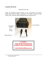
You can test the tape/pickup alignment by wiggling your finger between the tape 
and sensor. The tach reading should become live if your accelerometer is also 
plugged in. Also note that when aligned, a red light will glow on the back of the 
optical pickup. 


Remove the tape from metal props when finished to avoid corrosion under the 
tape. Use as little tape as possible (i.e. 1 inch strip) and mount the tape inboard 
toward that hub so the balance is not affected by removing the mass. 


Accelerometer Mounting 


The accelerometer mount MUST be short, and rigid. If the results after weight 
additions don't make sense, your accelerometer/mount may be resonating. 


If the accelerometer cable is pointing away from the center of the hub, then the 
angle reported by the DynaVibe is the HEAVY spot (where to remove weight, or 
180 degrees from where to add weight). If you flip it so the accelerometer cable is 
pointing toward the hub, then the reading will indicate the light spot (where to 
ADD weight). 


If possible, align the axis of the accelerometer so it goes through the center of the 
hub. If you have to shift it more than an inch, review the DynaVibe manual for 
interpreting the phase angle. 


If a long mount is needed for the tach, make two mounts and keep the 
accelerometer mount short and stiff. 


Содержание DynaVibe Classic

Страница 1: ...DynaVibe Classic User Manual Version 1 09 Aug 2015 WWW RPXTECH COM...

Страница 2: ......

Страница 3: ...llation of Equipment 8 Remove Cowling 8 Mount the Accelerometer and Optical Pickup 8 Mount Reflective Tape on the Propeller 9 Using the DynaVibe 12 Attach the DynaVibe 12 Start Your Engine 13 Averagin...

Страница 4: ...re please use extreme caution Be very careful with cables and components especially on pusher type aircraft ALWAYS confirm the ignition is off before rotating the propeller Areas of this manual will h...

Страница 5: ...on causes accelerated wear and fatigue on equipment and passengers The negative effects of vibration can be reduced by dynamically balancing the aircraft s rotating assembly balancing the crank prop e...

Страница 6: ...ine Applicable procedure For aircraft or propeller manufacturers that provide procedures for dynamic balancing propeller balancing is not considered a major airframe alteration When approved aircraft...

Страница 7: ...quired There are instances where spinners have been installed in such a manner as to allow the front of the spinner to move relative to the propeller If the spinner structure has any flexibility it wi...

Страница 8: ...lugs to allow the engine to rotate freely If one blade is positioned differently from another this indicates that either the blade is bent or the installation is unacceptable Again a dynamic balancer...

Страница 9: ...y static balance weights Equipment Performance and Calibration Equipment used on certified aircraft must be inspected and calibrated The DynaVibe is available with National Institute of Standards and...

Страница 10: ...n and fuel are off prior to moving propeller CAUTION Rotate the propeller slowly to confirm clearance of all components When you add weight confirm that you have not introduced any clearance issues Co...

Страница 11: ...the engine The optical pickup should be mounted approximately six inches behind the back of the propeller The accelerometer should be mounted as far forward as possible for maximum sensitivity A commo...

Страница 12: ...ar that the optical sensor cannot obtain a reading from the tape Mount Reflective Tape on the Propeller By placing the small piece of reflective tape provided in the kit on only one propeller that pro...

Страница 13: ...the center of the tape The photo pickup is configured to pulse a small light on the back of the photo pickup When the photo pickup is correctly illuminating the reflective tape the back of the photo...

Страница 14: ...uired would be 1 9 inches Tape Length Required RPM 6 from hub center 12 from hub center 24 from hub center 500 0 2 0 4 0 8 1000 0 4 0 8 1 6 1500 0 6 1 2 2 3 2000 0 8 1 6 3 1 2500 1 1 9 3 8 3000 1 2 2...

Страница 15: ...rometer and optical pickup cables from the engine compartment The cables are keyed so look closely at the connectors before plugging them into the DynaVibe Back of DynaVibe CAUTION Verify that the are...

Страница 16: ...Vibe RPM reading is accurate relative to the displayed RPM If the RPM is erratic or incorrect this may indicate that the optical sensor is not properly in line with the reflective tape The DynaVibe wi...

Страница 17: ...engine to idle Allow the engine to run at the lower RPM for a short period of time to cool Limitations Correction weights should not be attached to a damaged or cracked spinner or spinner backplate Tr...

Страница 18: ...ght to remove from the heavy location add weight on the opposite side of the propeller indicated angle 180 For instance if the system is displaying 0 25IPS 90 this is the position of excess weight If...

Страница 19: ...likely that the readout would be 0 17IPS 90 This gives a good indication that the single washer corrected approximately 0 07IPS of vibration While this would imply that one could quickly add two addi...

Страница 20: ...er 3 16 Light washer AN960 10 0 9 Flat Washer 3 16 washer AN970 3 3 9 Flat Washer 3 16 washer AN365 1032A 2 2 Elastic Stop Nut 10 32 nut AN525 10R6 2 1 Washer Head Screw 10 32 x 3 8 screw AN525 10R7 2...

Страница 21: ...avoid corrosion under the tape Use as little tape as possible i e 1 inch strip and mount the tape inboard toward that hub so the balance is not affected by removing the mass Accelerometer Mounting Th...

Страница 22: ...s ambiguity is eliminated by simply measuring in the direction of prop rotation The engine RPM must be stable for a valid vibration reading Hold RPM as stable as possible when balancing The engine sho...

Страница 23: ...mperatures If cylinder temperatures are drastically different it may indicate bad spark plug wires fowled plugs intake leaks poor fuel distribution etc Verify that the spinner is balanced by placing i...

Страница 24: ...21 Guide to Dynamic Balancing V1 09 WWW RPXTECH COM We maintain troubleshooting and balancing tips on our website so they can be continually updated Check www rpxtech com dv tips for the latest tips...

Страница 25: ...ack 4 cowling 8 20 cracking 20 cylinder 20 Documentation 17 DynaVibe 6 12 13 14 15 FAA 3 4 5 Limitations 14 NIST 6 Pickup 8 Pitch 4 pre balance inspection 3 6 Propeller 3 4 9 14 Reflective Tape 9 serv...

Страница 26: ...To download and print this chart please visit WWW RPXTECH COM CHART...

Страница 27: ......

Страница 28: ...WWW RPXTECH COM...

Отзывы: