


8
Guide to Dynamic Balancing V1.09
WWW.RPXTECH.COM
Installation of Equipment
Remove Cowling
Remove the cowling, if needed, to gain access to the area immediately behind
the propeller. For typical power plant installations, this would require
removing the upper cowling of the aircraft, giving access to the top of the
engine.
While you have the cowling off, check all the accessories for secure
mounting. Any loose components such as an alternator, starter, etc
Mount the Accelerometer and Optical Pickup
The accelerometer and optical pickup are typically mounted on the top of the
engine. The optical pickup should be mounted approximately six inches
behind the back of the propeller. The accelerometer should be mounted as far
forward as possible for maximum sensitivity.
A common mounting technique is to remove one of the case bolts along the
top of the engine. Replace the bolt with the accelerometer and optical pickup
bracket installed under the bolt. Position the optical pickup such that the beam
projects onto the back of the blade or spinner backplate.
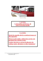
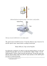
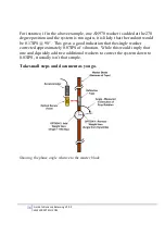
The following Figure shows the relationship between the optical pickup,
accelerometer, and the propeller. The optical pickup is pointing to the back of
the propeller onto the reflective tape (to be put on in the next step). The
accelerometer is mounted vertically, perpendicular to piston travel.
Содержание DynaVibe Classic
Страница 1: ...DynaVibe Classic User Manual Version 1 09 Aug 2015 WWW RPXTECH COM...
Страница 2: ......
Страница 26: ...To download and print this chart please visit WWW RPXTECH COM CHART...
Страница 27: ......
Страница 28: ...WWW RPXTECH COM...


