


WORKSHOP MANUAL BULLET
Page 74
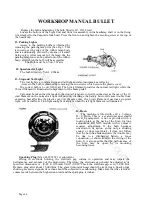
CARBURETTER
(BING)
The carburetter fitted to the engine is Bing Type 53/1 (Vehicles produced prior to middle of 1982
are fitted with Villiers carburetters).
1. DISMANTLING
In order to remove the carburetter from the engine, the air filter has to be disconnected from
carburetter. The carburetter stud nuts are then easily accessible which can be unscrewed and the
carburetter is removed from the engine.
2. DESCRIPTION OF BING CARBURETTER
This BING Carburetter Type 53/1 a semi-down draught slide carburetter with needle jet and slow
running control, has a 26.5 mm bore.
The float system controlling the flow of fuel from tank to carburetter, the main control system
with throttle slide, jet needle, needle jet, sprayer, Main Jet Carrier and main jet, the idling system with
idling jet, air adjusting screw and throttle stop, as well as the starting system comprising starting jet
(in the float bowl) and starting slide are housed in one single unit.
3. CONTROL OF FUEL FEED
The float of the carburetter consists of two plastic float bodies which are held by a common
hinge. It is installed centrally under the carburetter bore. In this way the carburetter can be
considerably inclined without influencing its function. The float maintains a constant fuel level in the
carburetter. When the fuel running-in reaches the required level the float is lifted and presses the float
needle against the needle seating, so that the flow of further fuel is stopped The engine drawing fuel
from the carburetter effects a lowering of the fuel level and the float drops, the float needle then opens
the needle seating so that the further fuel is allowed to enter from the tank.
The float bowl is secured to the carburetter body by means of a spring clip. There is a gasket
between the float bowl and the carburetter body. The space in the float chamber above the fuel level is
vented to the atmosphere through a hole. If this hole is clogged the float cannot rise due to the
formation of an air lock and causes the carburetter to flood. The above mentioned hole must therefore
be kept clean. There is, however, a second connection to the atmosphere so that the carburetter does
not fail completely even when the first vent hole is clogged or is filled with petrol due to inclination of
the vehicle.
The needle valve in conjunction with the float serves only to regulate the fuel feed and not as a
tap with a stopped engine. Tiny foreign bodies may settle between needle seat and needle preventing
a complete closing of the valve. Therefore, when stopping the engine the fuel tap of the tank should
always be closed. The fuel should be cleaned by a filter which should be installed before the fuel
enters the carburetter. Of course, this filter must be cleaned from time to time.
When fitting a new float the fuel level must be adjusted. It is to be noted that to prevent the
influence of vibrations the float needle is fitted with a spring loaded head which must not be
depressed by the weight of the float when adjusting the fuel level. The tongue on the float hinge
which presses on the float needle must be bent so that the float bottom is parallel to the fuel level.
MAIN CONTROL SYSTEM
The quantity of mixture drawn in by the engine and therefore the engine power is controlled by
the size of the carburetter bore opened by the throttle slide. This slide is lifted by means of a cable
against the action of a coiled spring. The velocity of the air forms a vacuum in the carburetter bore
causing fuel to flow from the float bowl through the jet system into the bore.
After the fuel has gone through the main jet and Main Jet Carrier and entered into the needle jet
it is mixed with air which is coming in from the primary air hole into an annulus around the needle
jet. This quantity of air effects the atomization of the fuel drawn in and consequently allows more
effective combustion in the engine.
In the part throttle range, i.e. when the throttle slide is in a position between a quarter and three
quarters of its full lift there will, depending on the slide position, be a need for less fuel than at full
speed. The reduction necessary for this is obtained by jet needle connected to the throttle slide and
entering into the needle jet. Depending on the taper measurements at the end of the jet needle a
bigger or smaller annular opening between needle and needle jet is formed. The jet needle can be
fixed in the throttle slide in three different positions which according to the taper position controls the
amount of fuel drawn in. For example "Needle position 2'' signifies that the jet needle is suspended in
www.hitchcocksmotorcycles.com
Содержание 350 BULLET 1989
Страница 9: ...WORKSHOP MANUAL BULLET Page 9 w w w h i t c h c o c k s m o t o r c y c l e s c o m ...
Страница 17: ...w w w h i t c h c o c k s m o t o r c y c l e s c o m ...
Страница 34: ...WORKSHOP MANUAL BULLET Page 34 w w w h i t c h c o c k s m o t o r c y c l e s c o m ...
Страница 37: ...w w w h i t c h c o c k s m o t o r c y c l e s c o m ...
Страница 41: ...WORKSHOP MANUAL BULLET Page 41 w w w h i t c h c o c k s m o t o r c y c l e s c o m ...
Страница 58: ...WORKSHOP MANUAL BULLET Page 58 w w w h i t c h c o c k s m o t o r c y c l e s c o m ...
Страница 69: ...WORKSHOP MANUAL BULLET Page 69 w w w h i t c h c o c k s m o t o r c y c l e s c o m ...
Страница 73: ...w w w h i t c h c o c k s m o t o r c y c l e s c o m ...
Страница 77: ...w w w h i t c h c o c k s m o t o r c y c l e s c o m ...
Страница 103: ...w w w h i t c h c o c k s m o t o r c y c l e s c o m ...
Страница 105: ...w w w h i t c h c o c k s m o t o r c y c l e s c o m ...
Страница 107: ...WORKSHOP MANUAL BULLET Page 107 w w w h i t c h c o c k s m o t o r c y c l e s c o m ...
Страница 108: ...WORKSHOP MANUAL BULLET Page 108 w w w h i t c h c o c k s m o t o r c y c l e s c o m ...
Страница 109: ...WORKSHOP MANUAL BULLET Page 109 w w w h i t c h c o c k s m o t o r c y c l e s c o m ...
Страница 110: ...WORKSHOP MANUAL BULLET Page 110 w w w h i t c h c o c k s m o t o r c y c l e s c o m ...
Страница 111: ...WORKSHOP MANUAL BULLET Page 111 w w w h i t c h c o c k s m o t o r c y c l e s c o m ...
Страница 113: ...WORKSHOP MANUAL BULLET Page 113 w w w h i t c h c o c k s m o t o r c y c l e s c o m ...


