Profibus DP Mk2 Option Card Installation Manual
56 of 84
Publication PUB088-005-00_1017
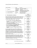
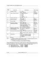
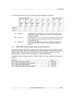
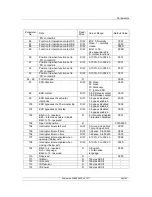
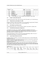
LED Description
State
Function
4
Diagnostic
Flash (Green)
Solid (Green)
Solid (Red)
Flash (Red)
PLC comms not present
Data being exchanged with PLC
Fatal Error
After solid green shows comms lost
5
Channel 2 Data Exchange
On (Red)
Off
In data exchange mode with PLC
Not in data exchange mode
6
Channel 2 RTS line
On (Red)
Off
Ready to reply to PLC
Not ready to respond
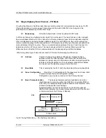
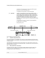
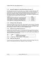
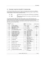
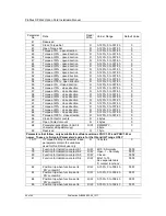
6.7 Basic Operation on Start up
Whenever a field device is powered up and it is found by the PLC it will
go through the standard Profibus procedure of Parameterisation and
Configuration before commencing Data Exchange. This exchange can
include altering the address if the device has an address of 126 and
the master supports address changes
– master class 2.
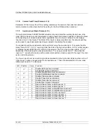
1) The first message
– master sends a
DIAG_req
telegram.
2) The response should be a
DIAG_res
with diagnostic data
attached.
3) If this is correct a
Set_Parameter
telegram is sent with the
parameterisation data attached.
4) The response should be a
Short Ack
message.
5) If a correct response is received a
Check_Config
telegram is sent
6) The response should be a
Short Ack
message.
7) If this is correct a
DIAG_req
telegram is sent.
8) The response should be a
DIAG_res
with diagnostic data
attached.
9) If DIAG is not reporting an error data exchange commences.
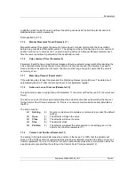
The Parameterisation data is extracted from the GSD file for the
particular address of the slave device. The association between the
GSD to be used and the address is made in the master during the
configuration of the network on the master (a table is created). The
association can also be defined in a Master 2 and sent to a Master 1 by
the master to master comms. Most master 1 devices permit the same
device type (as described in the GSD) to have different GSD files, so
allowing the GSD to be edited.
Editing the GSD file guarantees that a device coming on line after
having been switched off will have the correct settings. If FDT or PDM
changes the same parameters as those installed by a GSD then the
GSD values will replace those set by the FDT or PDM when the device
is switched off and on again, or the PLC is powered off and back on,
unless GSD parameterisation is not permitted.
(See section 5.4 for information on the Configurations allowed).
Fig 36: Profibus Start Up Sequence

