Profibus DP Mk2 Option Card Installation Manual
70 of 84
Publication PUB088-005-00_1017
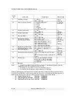
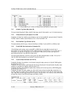
Parameter
No.
Data
Read /
Write
Value / Range
Default Value
115
ID Option1
R
16bytes ASCII
-
116
ID Option 2
R
16bytes ASCII
-
117
ID Option 3
R
16bytes ASCII
-
118
ID Option 4
R
16bytes ASCII
-
119
Manufacture notes
R
48bytes ASCII
-
120
General Notes
R/W
67bytes ASCII
-
Note:
- Only readable by V1 comms on Simple Dual and RedCom Dual modules.
7.2.1
Actuator Tag Data (Parameter 20)
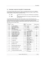
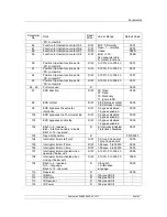
This parameter allows the Profibus card to hold a tag name for the actuator, up to 12 characters long.
7.2.2
Software Versions (Parameter 21 and 22)
Parameter 21 holds the Interface card software version in the form MXXX and parameter 22 holds the
Profibus network interface card software version in the form PNIC X.XX
7.2.3
Field Interface Type (Parameter 24)
This parameter reports the type of network interface card fitted. It will read 02 for a Profibus card.
7.2.4
Permit GSD Parameterisation (Parameter 25)
If the Profibus card has been set up using FDT or PDM it may be desirable to prevent any of
parameters 1 to 19 from being altered by the GSD file during normal start up or on a power cycle. If
the actuator is switched off, then back on, the standard Profibus start up routine will impose the
parameter values set in the GSD file for the device.
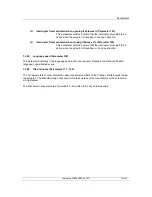
This parameter allows the card to be set to ignore the GSD parameterisation routine. If it is set to ‘1’
then the GSD Parameterisation is permitted. The default value is 1.
7.2.6
Control Outputs (Parameter 26 to 29)
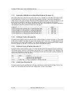
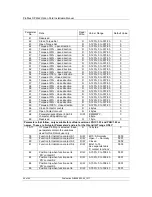
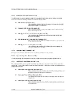
Parameter 26 allows the actuator to be controlled using the same values as in the ACTCON register
described in section 5.1.2.
Parameter 27 (in conjunction with Parameter 26) allows the actuator to be positioned using the same
values as in the POS_DV register, refer to section 5.1.3.
Parameter 28 allows the multiport actuator to be positioned for control as with the PORTCM register
as described in section 5.1.5.
Parameter 29 allows the relay outputs of an IQ or IQT to be controlled as described in section 5.1.4
and also allows the values in the contactor start counters to be reset to zero and the data logger to be
reset. Resetting the data logger clears all the values currently stored in the memory on the main board
and also the values in the historical torque and starts counters.
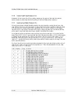
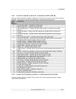
Parameter 29
Bit
13 - 15
12
11
10
4 - 9
3
2
1
0
Function
Reserved
Reset
data
logger
Clear
close
counter
Clear
open
counter
Reserved
DO-4
control
DO-3
control
DO-2
control
DO-1
control

