Profibus DP Mk2 Option Card Installation Manual
66 of 84
Publication PUB088-005-00_1017
7.1.13
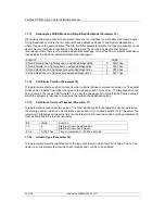
Redundancy FR/SR Mode and Simple/RedCom Mode (Parameter 15)
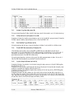
When using either type of dual channel card there are two methods for redundancy that can be used,
Flying Redundancy, where the two channels have addresses 64 apart, and System Redundancy,
where they have the same address. The first bit of this parameter selects the type of redundancy to be
used. The way that data is reported can be altered and the second bit selects either Simple
redundancy where there is no extended diagnostics message, or fully RedCom compliant redundancy
that includes the RedCom extended diagnostics messages.
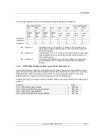
Function
Value
SR and Simple, two highways and no extended diagnostics
0
0000 hex
FR and Simple, one highway and no extended diagnostics
1
0001 hex
SR and RedCom, two highways plus extended diagnostics
2
0010 hex
FR and RedCom, one highway plus extended diagnostics
3
0011 hex
7.1.14
Part Stroke Position (Parameter 16)
This parameter sets the position to travel to when a Partial Stroke command is carried out. The partial
stroke can be initiated from either the open or the closed position of the valve. The target position can
be any value in the range 1-99% where 1 % is near the closed position. Note that the desired value to
which the actuator is required to move must be outside the deadband setting.
7.1.15
Part Stroke Limit and Timeout (Parameter 17)
This parameter is used to set two values. The most significant bit in the register is used to determine
the starting position, which can be either the open position (1) or closed position (0) for the valve. The
remaining 7 bits are used to set the time limit before which the required position (set by parameter 16)
must be achieved if the test is successful.
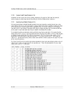
Bit
Value
Function
15
0
Start test from closed position
1
Start test from open position
0-14
0-7FFF hex
Time to complete, 0
– 32676 seconds
7.1.16
Actuator type (Parameter 18)
This parameter allows the identification of the type of actuator in which the PFU is fitted. This can be
useful on some systems to allow the correct display and controls to be enabled.

