

4
UltraVista Installation and Operations Manual
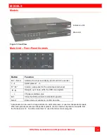
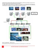
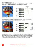
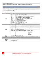
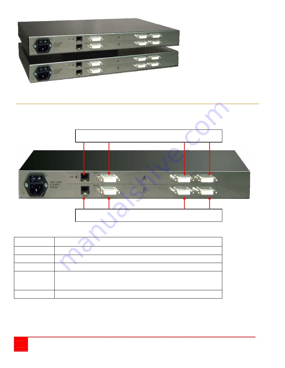
Extension Unit
Main Unit
Figure 2. Rear View
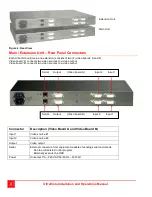
Main / Extension Unit – Rear Panel Connectors
Each UltraVista unit (main and extension) consists of two (2) video boards, A and B.
Video board “A” connects two video sources to a video output
Video board “B” connects two video sources to a video output
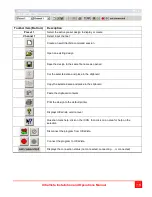
Connector
Description (Video Board A and Video Board B)
Input 1
Video source #1
Input 2
Video source #2
Output
Video output
Serial
External connection from equipment capable of sending serial commands
Run the UltraVista Control program
Externally execute the OSD
Power
Universal 110 – 240 VAC 50-60 Hz – 40 Watt
Serial Output (Video board A) Input 2 Input 1
Serial Output (Video board B) Input 2 Input 1
Содержание UltraVista
Страница 31: ...26 UltraVista Installation and Operations Manual ...
Страница 32: ...UltraVista Installation and Operations Manual 27 ...
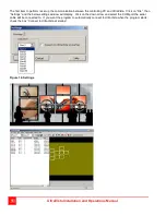
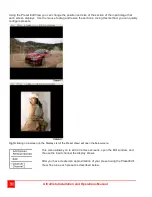
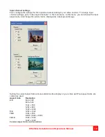
Страница 33: ...28 UltraVista Installation and Operations Manual Example ...
Страница 57: ... 103 0014 東京都中央区日本橋蛎殻町 1 16 11 TEL 03 3668 8089 FAX 03 3668 9872 URL http www cybernetech co jp ...


