background image

Controller functions

Version 1

RES-430

Page 47

10.8

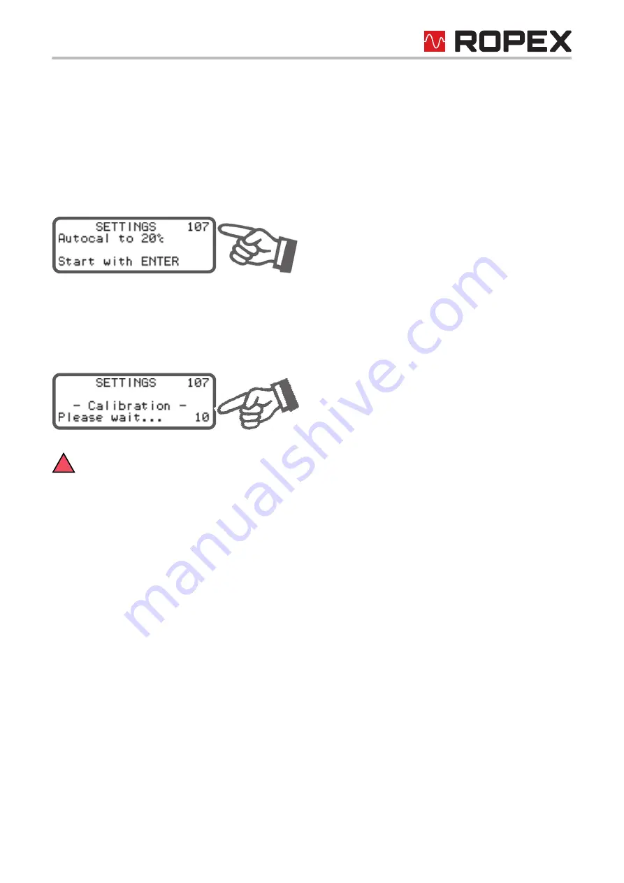
Automatic zero calibration (AUTOCAL)

Owing to the automatic zero calibration (AUTOCAL) function, there is no need to adjust the zero point manually
on  the  controller.  The  "AUTOCAL"  function  matches  the  controller  to  the  current  and  voltage  signals  that  are
present in the system. You can activate this function by selecting step 107 in the Settings menu and then pressing
the "ENTER" key. The initial temperature (ambient temperature) of the heatsealing bar(s) which is currently valid
for calibration can be set beforehand in the 0…40°C range using the "UP" and "DOWN" keys.
The zero point is calibrated in the factory to 20°C.

The automatic calibration process takes around 10…15 seconds. The heatsealing band is not heated until the cali-
bration process has finished.
The message "- Calibration - Please wait..." appears on the display while the "AUTOCAL" function is executing
and a counter counts down from 14 to 0. The actual value output (terminals 10+11) is set to 0°C (corresponds to
0 VDC) for the duration of the calibration process.

You should always wait for the heatsealing band and the bar to cool down (to ambient temperature)
before activating the "AUTOCAL" function.

Reasons for locked AUTOCAL function:

1. The "AUTOCAL" function cannot be activated if the heatsealing band cools down at a rate of more than 0.1K/

second. This is additionally indicated with step 107 in the Settings menu by the message "Heatsealing band

still hot! Please wait...".

2. If the "START" signal (HEAT) is activated, the "AUTOCAL" function is not executed. This is additionally indi-

cated with step 107 in the Settings menu by the message "Autocal locked! (START sig. active)".

3. The AUTOCAL function cannot be activated if a fault with error code 101…103, 201…203, 8xx or 9xx occurs

(

section 10.21 "Error messages" on page 60).

!

Содержание Resistron RES-430 Series

Страница 1: ...ro calibration AUTOCAL Automatic optimization AUTOTUNE Automatic phase angle compensation AUTOCOMP as of software revision 100 Automatic frequency adjustment Secondary control Heatsealing band alloy and temperature range selectable Time control heatsealing time and cooling time settable Configurable relay output e g end of cycle Time or temperature controlled cooling phase 0 10VDC analog output fo...

Страница 2: ...oad cell interface temperature sensor 31 9 6 Heatsealing band 35 9 7 Startup procedure 35 10 Controller functions 38 10 1 Indicators and controls 38 10 2 Display 38 10 3 Navigation in the menus 40 10 4 Menu structure 42 10 5 Two digit numbering system up to soft ware revision 006 44 10 6 Temperature setting set point selection 45 10 7 Temperature indication actual value output 45 10 8 Automatic ze...

Страница 3: ...basic prerequisite for reliable and safe operation of the system is the use of suitable heatsealing bands The resistance of the heatsealing band which is used must have a positive minimum temperature coefficient in order to guarantee trouble free operation of the RESISTRON temperature controller The temperature coefficient must be specified as follows e g Alloy A20 TCR 1100 ppm K LEX3500 TCR 3500 ...

Страница 4: ...d and operationally ready system in the machine with regard to its conformity with the safety provisions and the EMC directive see also section 8 3 Power supply If peripheral components e g the transformer or the line filter from other manufacturers are used no functional guarantee can be provided by ROPEX 1 6 Warranty provisions The statutory provisions for warranties apply for a period of 12 mon...

Страница 5: ... of the heatsealing bands and teflon coatings Simple operation and control of the sealing process 3 Principle of operation The resistance of the heatsealing band which is temperature sensitive is monitored 50x per second 60x at 60Hz by measuring the current and voltage The temperature calculated with the help of these measurements is dis played and compared with the set point The secondary voltage...

Страница 6: ...sented on an LC display with 4 lines and 20 characters Various display languages can be selected The real heatsealing band temperature is visualized on the display both as a digital number in C and in the form of a dynamic bar In addition to the digital and bar indications on the display the ACTUAL temperature of the heatsealing band is supplied to an analog 0 10VDC output The real heatsealing ban...

Страница 7: ...erial piggyback module is supplied with spacers for installation on the motherboard of the RES 430 Proceed as follows to install it Schematic diagram Female connector 5 pole Male connector 5 pole 9 pole sub D socket for serial data cable 4x spacer RES 430 motherboard Piggyback module Latching Snap on Fit the 4 spacers to the of the latching side motherboard first Then attach the piggyback module t...

Страница 8: ...motherboard of the RES 430 controller as standard It can be retrofitted in older controllers section 13 How to order on page 66 Only a ROPEX communication interface is allowed to be connected to the DIAG interface Con necting another device e g a telephone cable could damage the controller and result in malfunc tions The ROPEX communication interface CI USB 1 is described in a separate document Pi...

Страница 9: ...UAL temperature closing force You can export the data as a CSV file for further pro cessing in another PC program Female connector 5 pole Male connector 5 pole 6 pole socket for connection of CI USB 1 4x spacer RES 430 motherboard Piggyback module Latching Snap on Fit the 4 spacers to the of the latching side motherboard first Then attach the piggyback module to the with the 6 pole socket snap on ...

Страница 10: ...nterface Page 10 RES 430 Version 1 In addition the software permits the values in the Configuration and Settings menus to be transferred to the con troller or read from it The visualization software is described in a separate document ...

Страница 11: ...efficient 1100ppm Alloy A20 0 300 C Heatsealing band voltage secondary voltage of impulse transformer 12 42VAC Max load current max secondary cur rent of impulse trans former Terminals 5 6 7 8 Two heatsealing bands Isec max 90A per heatsealing band Imax 45A One heatsealing band Isec max 70A If only one heatsealing band is used terminals 7 8 must be externally jumpered with a high current cable in ...

Страница 12: ...aracters Power dissipation max 40W Ambient temperature 5 45 C Degree of protection Motherboard IP00 Display terminal Front IP42 IP65 with transparent front cover Art No 887000 Back IP20 Installation Motherboard 6 fixing holes diameter 3 2mm for screw mounting Display terminal Installed in front panel cutout with W x H 138 0 2 x 68 0 2 mm Fastened with clamps Weight Motherboard Approx 0 5kg incl co...

Страница 13: ...gth of 6mm must be used to fasten the printed circuit board on the underside All national and international regulations must be complied with Connector Piggyback module 6 x fixing hole optional data interface for T 430 terminal Specified component heights for connectors incl plug in parts 105 0 210 0 110 0 3 0 3 0 3 0 3 0 Diameter 3 2mm ...

Страница 14: ...ut Page 14 RES 430 Version 1 7 2 Display terminal 144 72 Outline dimensions of front frame Panel cutout 138 x 68 0 2 0 2 4 58 9 136 66 144 Front panel Connecting cable length 250mm Rubber seal Mounting clamp Connector Front frame ...

Страница 15: ...e information pro vided in section 8 2 Installation steps on page 15 must be heeded additionally Check the tightness of all the system connections including the terminals for the impulse trans former windings 6 Make sure that the wiring conforms to the relevant national and international installation regulations 8 2 Installation steps The following points should be heeded in addition to the inform...

Страница 16: ...Installation Page 16 RES 430 Version 1 Push on connectors on the sealing bar can lead to loose contacts Use cables with screw connections ...

Страница 17: ... machine wiring ROPEX Application Report Do not run the filter supply wires line side parallel to the filter output wires load side RESISTRON temperature controller RES 430 Impulse Transformer Designed according to VDE 0570 EN 61558 isolating transformer with reinforced insulation Connect core to ground Use transformers with one section bobbin The power duty cycle and voltage values must be deter ...

Страница 18: ...a high current cable in order to avoid malfunctions or damage of the controller Step 240 in the Configuration menu must be set to Double for this purpose Band 1 Band 2 Heatsealing band Load cell interface and temperature sensor FOOT SWITCH Main switch Impulse transformer ANALOG OUTPUT ACTUAL temperature of heatsealing band 0 10VDC GND Earth Over current protection Double pole circuit breaker or fu...

Страница 19: ...face and temperature sensor IMPORTANT If only ONE heatsealing band is used output terminals 7 8 must be jumped with a high current cable in order to avoid malfunctions or damage of the controller Step 240 in the Configuration menu must be set to Double for this purpose Line Solenoid ANALOG OUTPUT ACTUAL temperature of heatsealing band 0 10VDC Over current protection Double pole circuit breaker or ...

Страница 20: ... operation 9 1 View of the controller 9 1 1 Motherboard 9 1 2 Front view of the terminal Connector for terminal Terminals Nameplate Terminals Connector for piggyback module optional data interface Nameplate Connecting cables Operator keys Mounting clamps Display ...

Страница 21: ... As of software revision 100 also French Spanish Dutch Danish Finnish Swedish Greek Turkish Portugese The language which is selected in this menu remains set even if the factory settings are restored step 202 in the Configuration menu 9 2 2 Restoring the factory settings The internal controller settings can be reset to the factory settings with step 202 in the Configuration menu Only the language ...

Страница 22: ...can be set with step 205 in the Configuration menu You can select a temperature range of 200 C 300 C Factory setting 400 C or 500 C 9 3 Time control timer function 9 3 1 Activation and indication The settings described here are only allowed to be entered by technically trained persons An incor rectly parameterized timer function may cause disruptions to operation and damage to the machine The time...

Страница 23: ...r or by deactivating the START signal If the display is in the home position the individual timeouts can be monitored there The remaining heatsealing time is indicated on the display in the form of a countdown at the end of the heating phase A direction arrow indicates the active process The active cooling phase is subsequently marked with the direction arrow at the end of the heating phase The di...

Страница 24: ...able with these advanced settings are described below 9 3 2 Setting the starting delay The start of the heating process can be explicitly delayed by entering a starting delay time with step 103 in the Settings menu e g in order to bridge the closing time of the heatsealing bars When the START signal is activated the controller waits for the time specified with this menu step to elapse before comme...

Страница 25: ...temperature of the heatsealing band falls below a specified tem perature value TK This cooling temperature can be set with step 105 in the Settings menu 2 Relative The cooling phase ends when the ACTUAL temperature falls to a value corresponding to X of the SET tem perature This percentage cooling value can be set with step 105 in the Settings menu Example SET temperature 180 C cooling value 60 Co...

Страница 26: ...lows 1 Cooling temp in C if setting with menu step 210 Absolute The cooling phase of the internal timeout ends when the ACTUAL temperature of the heatsealing band falls below the SET temperature The minimum settable temperature is 50 C This is also the factory setting The maximum value of the setting range is limited either by the maximum value specified with step 206 in the Configuration menu or ...

Страница 27: ...u step 103 If the starting delay 0s the heatsealing time begins as soon as the START signal is activated 2 When temperature reached Factory setting Once again the heating process starts as soon as the set starting delay elapses Settings menu step 103 The specified heatsealing time does not start however until the ACTUAL temperature of the heatsealing band reaches 95 of the SET temperature These tw...

Страница 28: ...eating phase and opens again at the end of the cooling phase This configuration permits air cooling to be activated with relay K1 or the solenoid drive during the cooling phase for instance 4 End of cycle impulse The normally open contact of relay K1 or the solenoid drive closes at the end of the parameterized timeout i e at the end of the cooling phase and opens again after approximately 500ms If...

Страница 29: ...nd upper limits of the tolerance band can be changed by means of steps 207 208 in the Configuration menu factory setting 10K respecitvely 10K If the actual temperature is outside the specified tolerance during the parameterized monitoring time the heat sealing cycle is immediately interrupted and the corresponding error code 307 308 is indicated section 10 21 Error messages on page 60 This monitor...

Страница 30: ...ure diagnosis activated If the temperature diagnosis is not activated byl the end of the configured sealing time i e if the ACTUAL temper ature does not exceed the upper or lower tolerance band limit the corresponding error code 309 310 is indi cated If the temperature diagnosis function is activated an additional delay time between 0 and 9 9s can be parameter ized for temperature monitoring with ...

Страница 31: ...ected to a load cell and a temperature sensor The load cell is used to measure the closing force of the heatsealing mechanism This force can be monitored by the controller during the heatsealing cycle If the closing pressure is outside the specified limit values the heatsealing cycle is interrupted and an alarm is indicated on the display The temperature sensor can be used to monitor either the in...

Страница 32: ...Up to software revision 007 The force diagnosis begins 100ms after the ACTUAL temperature reaches 95 of the SET temperature and con tinues until the end of the parameterized cooling phase As of software revision 008 The force diagnosis function can be additionally parameterized by means of step 247 in the configuration menu The following settings are possible 1 OFF Factory setting Force diagnosis ...

Страница 33: ...tered with step 245 A straight force measurement curve is assumed between these two measuring points tare weight and reference force The measured force is only indicated if it is within the permissible limit values If the upper or lower limit value is exceeded the following information is indicated on the display Measured force Indication on display Error code if force diagnosis is active Minimum ...

Страница 34: ...mperature sensor is not connected or if the sensor connecting cable is defective an alarm is output by the controller after 3s assuming the temperature sensor has been activated with step 241 The sensor temperature measurement described here serves to monitor and or limit the load cell or machine temperature It cannot be used to monitor the temperature of the heatsealing band or for temperature co...

Страница 35: ...ered irreversibly 9 6 2 Burning in the heatsealing band If a new heatsealing band has been used the zero point is first of all calibrated while the band is still cold by acti vating the AUTOCAL function on the controller When the AUTOCAL function has finished the display shows the preselected calibration temperature default value 20 C Adjust the set point to approximately 250 C and press the HAND ...

Страница 36: ... the ROPEX Application Report as well as the specifications for the heat sealing band that is used section 9 2 General controller configuration on page 21 4 Make sure that a START signal is not present 5 Switch on the line voltage 6 A power up message appears on the display for approximately 2 seconds when the controller is switched on to indicate that it has been started up correctly 7 One of the...

Страница 37: ...ted successfully the main menu appears on the display again Then specify a defined temperature heatsealing temperature with step 101 in the Settings menu and activate the START signal HEAT Alternatively you can start a heatsealing process by pressing the HAND key assuming step 213 has not been locked in the Configuration menu and the display is in the home position The indication of the ACTUAL tem...

Страница 38: ...ears on the display for approximately 2 seconds when the controller is switched on This message also includes details of the software version ENTER HAND RESET ROPEX RESISTRON RES 4 MENU key for advancing to next menu step or switching menu 2 sec Press Next menu step 1 2 sec Press Return to previous position as of SW Revision 100 2 sec Press Hold Return to home position ENTER key ENTER function HAN...

Страница 39: ...u structure on page 42 10 2 4 Error message The fault diagnosis function of the controller is always active If a fault is detected it is indicated on the display immediately in the form of an error message section 10 20 System monitoring alarm output on page 60 Icon indicates that NO contact of additional Specified heatsealing temperature SET temperature relay K1 is closed Measured ACTUAL temperat...

Страница 40: ...from anywhere in the menu structure providing a controller alarm is not active In this case the Alarm menu is opened instead If the display is in the home position or an alarm is indicated and you press the MENU key for longer than 2s you are taken directly to the configuration level starting at step 201 In addition you always return to the home position if you do not press any keys for a period o...

Страница 41: ...by briefly pressing the MENU key 2s You can then activate the AUTOCAL function by pressing the ENTER key section 10 8 Automatic zero calibration AUTOCAL on page 47 If you press the MENU key for longer than 2s in the Alarm menu you are taken directly to the configuration level starting at step 201 You can return from the Configuration menu to the Alarm menu either by pressing the MENU key for longe...

Страница 42: ... function 213 Lock HAND key 207 Set point reached 205 Temperature range Settings Configuration 1 Force sensor active 2 Force sensor not active 3 Time control OFF 4 Time control ON 5 TCR not variable 6 TCR variable 7 Cooling mode abso lute relative time 8 Cooling mode none 211 Start of sealing time Fault 215 Alarm relay Display actual force 1 2 204 Temp coefficient 214 Cycles 107 Autocal 102 Prehea...

Страница 43: ...s 244 Force tare Configuration 1 Force sensor or force and tem perature sensor active 2 Temp sensor active 3 No sensors active 4 Temp sensor not active 243 Maximum force 1 2 249 Foot switch hold time Continued from previous page 246 Max sensor temp 3 2 4 Back to home position 221 Autocomp 220 Meas imp length 219 Heatup timeout 222 Output 1 240 Sealing mode s d ...

Страница 44: ...tion on page 20 or section 10 4 Menu structure on page 42 Menu Menu step Numbering up to SW revision 006 Numbering as of SW revision 007 Settings menu Heatsealing temperature 1 101 Starting delay 3 103 Heatsealing time 4 104 Cooling value 5 105 Hold mode 6 106 AUTOCAL 7 107 Configuration menu Language 20 201 Factory settings 21 202 Alloy TCR 22 203 Var temp coeff 23 204 Temperature range 24 205 Ma...

Страница 45: ...213 has not been locked in the Configuration menu and the display is in the home position is pressed The set heatsealing temperature is displayed in the main menu once it has been entered 10 7 Temperature indication actual value output If the display is in the home position the ACTUAL temperature is indicated there as a digital value and as a dynamic bar The heating and control process can thus be...

Страница 46: ...f an alarm is signaled this analog output is used in addition to the value indicated on the controller to display a selective error message section 10 21 Error messages on page 60 This output is not potential free and could have the potential of the secondary voltage of the impulse transformer External grounding is not allowed If this warning is ignored the controller will be dam aged by frame cur...

Страница 47: ...ed The message Calibration Please wait appears on the display while the AUTOCAL function is executing and a counter counts down from 14 to 0 The actual value output terminals 10 11 is set to 0 C corresponds to 0 VDC for the duration of the calibration process You should always wait for the heatsealing band and the bar to cool down to ambient temperature before activating the AUTOCAL function Reaso...

Страница 48: ...e for FOOT SWITCH signal A hold time between 0 and 2 0s can be parameterized for the FOOT SWITCH signal with step 249 in the Con figuration menu The relay or the solenoid drive remains closed for the parameterized time after this signal is activated even if the signal is deactivated again Among other things this permits the closing movement of the sealing jaws to be started by briefly activating a...

Страница 49: ... counter is reset to 0 if the ENTER key is pressed or if the maximum count of 999 999 999 cycles is exceeded 10 13 Single double sealing Step 240 determines how the two heatsealing bands are heated depending on the design of the machine or equipment If two heatsealing bands for top and bottom heating are installed in the machine one of these bands can be deac tivated for specific applications The ...

Страница 50: ...he last heatsealing phase is always indicated as a digital value When the controller is switched on or after an alarm is acknowledged the real ACTUAL temperature is indicated until the end of the first heating phase 3 2 s This setting causes the current ACTUAL temperature to be displayed as a digital value for an additional 2 seconds at the end of a heatsealing phase This temperature is then indic...

Страница 51: ...sation AUTOCOMP as of software revision 100 It may be necessary to compensate the phase angle displacement between the UR and IR measuring signals in certain heatsealing applications ROPEX Application Report The AUTOCOMP function is provided for this purpose It can be parameterized with step 221 as followed 1 OFF Factory setting ACTUAL temp START signal ON T t t OFF 0 Hold OFF T t 0 ACTUAL indicat...

Страница 52: ... AUTOCOMP Start with ENTER appears on the display during this time The subsequent AUTOCOMP function is executed in approximately 2 0s AUTOCOMP Please wait appears on the display during this time If the interval following the successful execution of the AUTOCAL function is longer than 2 0s the display returns to the home position and the AUTOCOMP function is not executed The actual value output ter...

Страница 53: ...the home position in other words it has no function As of softwarew revision 203 The HAND key function when the display is in the home position and the activation of the AUTOCAL function using step 107 can be configured with step 213 in the Configuration menu This prevents the heatsealing bands from being inadvertently heated if the HAND key is pressed and or the AUTOCAL function from being inadve...

Страница 54: ...tions Page 54 RES 430 Version 1 4 Lock HAND AUTOCAL The HAND key is locked when the display is in the home position in other words it has no function In addition the AUTOCAL function cannot be activated using step 107 ...

Страница 55: ... possible to disable all changes to values parameters in the Configuration menu This prevents the controller configuration from being tampered with by unauthorized persons The Configuration menu can be locked or unlocked by pressing the MENU key for 2seconds while the power up message is displayed after switching on the controller section 10 2 1 Power up message on page 38 The display then shows a...

Страница 56: ...itched to a standby mode No more heatsealing processes take place and no more measuring impulses are generated The display changes to indicate this The main menu is displayed again and operation is resumed when the input voltage returns to the specified tol erance range The standby mode is indicated by 0 C corresponds to 0V at the analog output Trouble free operation of the controller is only guar...

Страница 57: ...l the foot switch can then be opened again but the jaws remain closed 3 The heating process must begin immediately without a starting delay 4 The heatsealing time t2 1s must begin when the ACTUAL temperature reaches 95 of the SET tempera ture T 180 C 5 The heatsealing bands are not heated any further at the end of the heatsealing phase i e at the end of the heatsealing time The cooling phase begin...

Страница 58: ... already have been entered The settings should be undertaken in the specified order Then Step in Configuration menu Setting 210 Cooling mode Absolute 211 Start of heatsealing time When temperature reached 212 Relay K1 function When start signal present Step in Settings menu Setting 101 Heatsealing tempera ture 180 C 103 Starting delay 0 0 s ACTUAL temp START signal 180 C t t OFF 0 80 C 1s t Open R...

Страница 59: ...Controller functions Version 1 RES 430 Page 59 104 Heatsealing time 1 0 s 105 Cooling value Cooling temperature 80 C Step in Settings menu Setting ...

Страница 60: ...t occurs the actual value output is used to display error codes in the event of an alarm 13 voltage levels are offered for this purpose in the 0 10VDC range each of which is assigned an error code section 10 21 Error messages on page 60 If a state that requires AUTOCAL occurs or if the controller configuration is incorrect error codes 104 106 111 114 or 211 the actual value output jumps back and f...

Страница 61: ...Temperature too high sec 9 4 Frequency fluctuation inadmissible line frequency Heatup time exceeded sec 9 4 1 Force sensor measure range overflow sec 9 5 3 Force sensor measure range underflow sec 9 5 3 Closing force too low sec 9 5 2 Closing force too high sec 9 5 2 Force sensor missing sec 9 5 3 Temperature sensor defective sec 9 5 4 Sensor temperature too high sec 9 5 4 Temperature sensor missi...

Страница 62: ...orrect Impulse transformer incorrectly sized Temperature too low Temperature too high Calibration failed loose contact ambient temperature fluctuations Data error Current signal incorrect calibration not possible Voltage signal incorrect calibration not possible Current and voltage signals incorrect calibration not Temperature fluctuations calibration not possible Temp 500 C C 266 500 300 500 333 ...

Страница 63: ...cuit delta R Heatsealing band partially bypassed by conducting part clamp opposite heatsealing bar etc Parallel circuit interrupted Wire break heatsealing band break Contacting to heatsealing band defective Total short circuit Heatsealing band installed incorrectly insulation at heat sealing bar ends missing or incorrectly installed Conducting part bypasses heatsealing band completely Controller v...

Страница 64: ...e temp coeff 1100ppm K Step 205 Temperature range 300 C Step 206 Maximum temperature 300 C Step 207 Set point reached 10K Step 208 Set point exceeded 10K Step 210 Cooling mode Absolute Step 211 Start of heatsealing time When temperature reached Step 212 Relay K1 function Active when START signal present Step 213 Lock HAND key and or the function AUTOCAL OFF Step 214 Cycle counter 0 Step 217 Temper...

Страница 65: ...er in this way 3 Restore customer settings Selecting this option restores the customer settings that were saved as described in 2 When the controller is first delivered the customer settings are identical to the Ropex settings After pressing the ENTER key in this menu step you are asked to confirm the new settings safety query Another message appears if you now confirm these settings by pressing t...

Страница 66: ...LF 06480 Continuous current 6A 480VAC Art No 885500 Impulse transformer See ROPEX Application Report for design and ordering information Optional serial RS232 data interface piggyback module Art No 743099 Sub D connecting cable for optional RS232 data interface for connection to piggyback module Length 2m Art No 884202 Length 5m Art No 884205 Length 10m Art No 884210 Optional DIAG interface piggyb...

Страница 67: ... 11 48 Force diagnosis 32 Force indication 33 Fuse 17 H HEAT 37 48 Heatsealing band type 11 Heatsealing time 25 Heatup timeout 31 Hold mode 50 Hold time for FOOT SWITCH signal 48 I Impulse heatsealing method 5 Impulse Transformer 17 Impulse transformer 66 Installation 12 15 Installation procedure 15 Installation regulations 15 L Line filter 17 66 Line frequency 6 11 Line voltage 11 Load cell inter...

Страница 68: ...control 5 Temperature diagnosis 29 Temperature indication 45 Temperature range 11 22 Temperature sensor 12 31 Temperature setting 45 Temperature unit 55 Transformer 3 17 66 Type of construction 11 U Undervoltage detection 56 V View 20 Visualization software 9 W Wiring 15 17 Wiring diagram with relay K1 18 Wiring diagram with solenoid drive 19 ...

Отзывы: