


28
GB
29
GB
OPERATING INSTRUCTIONS
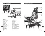
Ensure that any spacers and spindle rings that
may be required suit the spindle and the blade
fitted.
1) Make sure that the electrical plug is
removed from the power point.
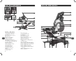
2) Push down on the operating handle (7)
and pull the release knob (6) to disengage
the saw arm (5). The release knob (6) can
be turned so that it is held in the retracted
position.
3) Raise the saw arm (5) to its highest position.
4) Using a Phillips head screwdriver loosen
and remove the screw that secures the
guard retraction arm (13) to the rotating
blade guard.
5) Using a Phillips head screwdriver loosen
and remove the screw that secures the
blade bolt cover (14).
6) Pull the rotating blade guard (12) down then
swing it up together with the blade bolt
cover (14). When the rotating blade guard
(12) is positioned over the upper fixed blade
guard (9) it is possible to access the blade
bolt.
7) Hold the rotating guard (12) up and press
the spindle lock button (26). Rotate the
blade until the spindle locks.
8) Use the 6mm hex key provided to loosen
and remove the blade bolt. (Loosen in a
clockwise direction as the blade screw has
a left hand thread).
9) Remove the flat washer and outer blade
washer and the blade.
10) Wipe a drop of oil onto the inner blade
washer and the outer blade washer where
they contact the blade.
11) Fit the new blade onto the spindle taking
care that the inner blade washer sits
behind the blade.
CAUTION.
To ensure correct blade rotation,
always install the blade with the blade teeth
and the arrow printed on the side of the blade
pointing down. The direction of blade rotation
is also stamped with an arrow on the upper
blade guard.
12) Replace the outer blade washer.
13) Depress the spindle lock button (26) and
replace the flat washer and blade bolt.
14) Use the 6mm hex key to tighten the blade
bolt securely (tighten in an anti-clockwise
direction).
15) Lower the blade guard, hold the rotating
lower blade guard (12) and blade bolt
cover (14) in position and tighten the fixing
screw.
16) Replace the guard retraction arm and
secure onto the rotating blade guard.
17) Check that the blade guard operates
correctly and covers the blade as the saw
arm is lowered.
18) Connect the saw to the power supply and
run the blade to make certain that it is
operating correctly.
Cross-cutting (without slide action)
When cutting a narrow piece of wood it is
not necessary to use the slide mechanism. In
these cases ensure that the slide lock (29) is
screwed down to prevent the saw arm from
sliding.
A crosscut is made by cutting across the grain
of the workpiece. A 90º crosscut is made with
the mitre table set at 0º. mitre crosscuts are
made with the table set at some angle other
than zero.
1) Pull on the release knob (6) and lift the saw
arm (5) to its full height.
2) Loosen the mitre lock (25).
3) Rotate the mitre table (21) until the pointer
aligns with the desired angle.
4) Retighten the mitre lock (25).
WARNING.
Be sure to tighten the mitre lock
before making a cut. Failure to do so could
result in the table moving during the cut and
cause serious personal injury.
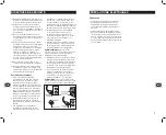
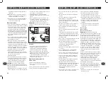
5) Place the workpiece flat on the table with
one edge securely against the fence (19).
If the board is warped, place the convex
side against the fence. If the concave side
is placed against the fence, the board could
break and jam the blade.
OPERATING INSTRUCTIONS
6) When cutting long pieces of timber, support
the opposite end of the timber with the side
support bars (37), a roller stand or a work
surface that is level with the saw table.
7) Use the clamp assembly (10) to secure the
workpiece wherever possible.
8) It is possible to remove the clamp assembly
(10) by loosening the clamp assembly lock
(11) and moving it to the other side of the
table. Make sure the clamp assembly lock is
tight before using the clamp.
9) Before turning on the saw, perform a dry run
of the cutting operation to check that there
are no problems.
10) Hold the operating handle (7) firmly and
squeeze the switch trigger (24). Allow
the blade to reach maximum speed and
slowly lower the blade into and through the
workpiece.
11) Release the switch trigger (24) and allow
the saw blade to stop rotating before
raising the blade out of the workpiece.
Wait until the blade stops before removing
the workpiece.
Cross-cutting (with slide action)
When cutting wide workpieces, first unscrew
the slide lock (29).
1) Pull on the release knob (6), raise the saw
arm (5) to its highest position and slide it
towards you.
2) Hold the handle firmly and squeeze the
switch trigger (24). Allow the blade to reach
maximum speed.
3) Slowly lower the blade into the workpiece
and slide it away from you at the same time
until the workpiece is cut.
4) Release the switch trigger (24) and allow the
saw blade to stop rotating before raising the
blade out of the workpiece. Wait until the
blade stops before removing the workpiece.
Bevel cut
A bevel cut is made by cutting across the
grain of the workpiece with the blade angled
to the fence and mitre table. The mitre table is
set at the zero degree position and the blade
set at an angle between 0º and 45º.
Use the slide action when cutting wide
workpieces.
1) Pull on the release knob (6) and lift the saw
arm to its full height.
2) Loosen the mitre lock (25).
3) Rotate the mitre table (21) until the pointer
aligns with zero on the mitre scale (22).
4) Retighten the mitre lock (25).
WARNING.
Be sure to tighten the mitre lock
before making a cut. Failure to do so could
result in the table moving during the cut,
causing serious personal injury.
5) Loosen the bevel lock (16) and pull out the
0º bevel adjuster. Move the saw arm (5) to
the left or right to the desired bevel angle
(between 0º and 45º). Tighten the bevel lock
(16).
6) Place the workpiece flat on the table with
one edge securely against the fence (19).
If the board is warped, place the convex
side against the fence. If the concave side
is placed against the fence, the board could
break and jam the blade.
7) When cutting long pieces of timber, support
the opposite end of the timber with the side
bars (36), a roller stand or a work surface
that is level with the saw table.
8) Use the clamp assembly (10) to secure the
workpiece wherever possible.
9) It is possible to remove the clamp assembly
(10) by loosening the clamp assembly lock
(11) and moving it to the other side of the
table. Make sure the clamp assembly lock is
tight before using the clamp.
10) Before turning on the saw, perform a dry
run of the cutting operation to check that
there are no problems.
11) Hold the operating handle (7) firmly and
squeeze the switch trigger (24). Allow
the blade to reach maximum speed and
slowly lower the blade into and through
the workpiece.
12) Release the switch trigger (24) and allow
the saw blade to stop rotating before
raising the blade out of the workpiece.
Wait until the blade stops before removing
the workpiece.
Содержание 2001574
Страница 17: ......


