background image

30

GB 

31

GB 

OPERATING INSTRUCTIONS

Compound mitre cut

A compound mitre cut involves using a mitre 
angle and a bevel angle at the same time. 
It is used in making picture frames, to cut 
mouldings, making boxes with sloping sides 
and for roof framing. Always make a test cut 
on a piece of scrap wood before cutting into 
the good material.
Use the slide action when cutting wide 
workpieces.
1)  Pull on the release knob (6) and lift the saw 

arm to its full height.

2)  Loosen the mitre lock (25). 
3)  Rotate the mitre table (21) until the pointer 

aligns with the desired angle on the mitre 
scale (22).

4)  Retighten the mitre lock (25).

WARNING. 

Be sure to tighten the mitre lock 

before making a cut. Failure to do so could 
result in the table moving during the cut, 
causing serious personal injury.
5)  Loosen the bevel lock (16) and pull out the 

0º bevel adjuster (18) and move the saw 
arm (5) to the left or right to the desired 
bevel angle (between 0º and 45º). Tighten 
the bevel lock (16).

6)  Place the workpiece flat on the table with 

one edge securely against the fence (19). 
If the board is warped, place the convex 
side against the fence. If the concave side 
is placed against the fence, the board could 
break and jam the blade.

7)  When cutting long pieces of timber, support 

the opposite end of the timber with the side 
bars (36), a roller stand or a work surface 
that is level with the saw table.

8)  Use the clamp assembly (10) to secure the 

workpiece wherever possible.

9)  It is possible to remove the clamp assembly 

(10) by loosening the clamp assembly lock 
(11) and moving it to the other side of the 
table. Make sure the clamp assembly lock is 
tight before using the clamp. 

10)  Before turning on the saw, perform a dry 

run of the cutting operation to check that 
there are no problems.

11)  Hold the operating handle (7) firmly and 

squeeze the switch trigger (24). Allow 
the blade to reach maximum speed and 
slowly lower the blade into and through the 
workpiece.

12)  Release the switch trigger (24) and allow 

the saw blade to stop rotating before 
raising the blade out of the workpiece. 
Wait until the blade stops before removing 
the workpiece.

Adjusting the laser lines

The lower laser is factory set to emit a laser 
line along the right-hand side of the blade. The 
upper laser is factory set to emit a laser line 
to the left-hand side of the blade. This upper 
laser can be adjusted by the operator to suit 
blades of different kerf widths.
To adjust the position of the upper laser, 
proceed as follows:
1)  Remove the laser cover by pulling it towards 

you.

2)  Switch on the laser lights with the on/off 

switch (2).

3)  Using a Phillips head screwdriver (not 

supplied), adjust the position of the line from 
the upper laser by turning the laser pitch 
control (4).

4)  Adjust until the left-hand laser line is aligned 

with the left-hand side of the blade.

5)  Switch off the laser lights.

Using the laser line generator

WARNINGS

Do not stare directly at the laser beam.
Never aim the beam at any person or an 
object other than the workpiece.
Do not deliberately aim the beam at personnel 
and ensure that it is not directed towards the 
eye of a person for longer than 0.25s.
Always ensure the laser beam is aimed 
at a sturdy workpiece without reflective 
surfaces. Wood or rough coated surfaces are 
acceptable. Bright shiny reflective surfaces 
are not suitable for laser use as the reflective 
surface could direct the beam back at the 
operator.

GUARANTEE

Always remember to switch off the laser on/off 
switch (2) after finishing a job. Only turn the 
laser beam on when the workpiece is on the 
mitre saw table.
1)  Mark the line of the cut on the workpiece.
2)  Adjust the angle of mitre and bevel of the 

cut as required.

3)  Switch on the laser light on/off switch (2).
4)  Clamp the workpiece in position using the 

laser lines to align the blade with the pencil 
mark on the workpiece.

NOTE. 

To cut to the left-hand side of the 

blade, align the left-hand laser line with the 
pencil mark. To cut to the right-hand side of 
the blade, align the right-hand laser line with 
the pencil mark.
5)  Plug in the machine and start the motor.
6)  When the blade is at its maximum speed 

(approximately 2 seconds), lower the blade 
through the workpiece.

7)  After completing the cut, switch off the laser 

light on/off switch (2).

8)  After each use, clean the laser light 

assembly (1) as described below:

9)  Switch off the laser light switch (2) and then 

remove the plug from the power point.

10)  With the saw arm (5) in the raised position, 

use a soft brush to dust away the sawdust 
build-up around the assembly.

NOTE.

 Wear eye protection whilst brushing 

the dust away.

Maintenance

1)  Store the tool, instruction manual and 

accessories in a secure place. In this way 
you will always have all the information and 
parts on hand.

2)  Keep the tool’s air vents unclogged and 

clean at all times.

3)  Remove dust and dirt regularly. Cleaning  

is best done with compressed air or a rag.

4)  Never use caustic agents to clean  

plastic parts.

5)  Lubricate the guide roller from time to time 

with a drop of oil. It will extend the life of 
the roller.

CAUTION. 

Do not use cleaning agents to 

clean the plastic parts of the tool. A mild 
detergent on a damp cloth is recommended. 
Water must never come into contact with  
the tool.

General inspection

Regularly check that all the fixing screws are 
tight. They may vibrate loose over time. 

Guarantee

Thank you for investing in a RONA power 
tool. These products have been made to 
demanding, high-quality standards and 
are guaranteed for 

domestic use

 against 

manufacturing faults for a period of  
36 months from the date of purchase. 
This guarantee does not affect your  
statutory rights. In case of any malfunction of 
your RONA tool (failure, missing part, etc.), 
please contact one of our service technician 
at our toll free service line at  
1-888-874-8661 from 9 am to 9 pm,  
Monday to Friday, Eastern time.
Normal wear and tear, including accessory 
wear, is not covered under guarantee. The 
product is guaranteed for 36 months if used 
for normal trade purposes. Any guarantee is 
invalid if the product has been overloaded 
or subject to neglect, improper use or an 
attempted repair other than by an authorised 
agent. Heavy duty, daily professional or hire 
usage are not guaranteed. Due to continuous 
product improvement, we reserve the right  
to change the product specification without 
prior notice.

Содержание 2001574

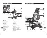
Страница 1: ...l F GB 2 17 18 32 SCIE À ONGLETS COMBINÉE 12 PO COULISSANTE À DOUBLE BISEAU AVEC LASER REDEYE 2001574 DOUBLE BEVEL SLIDE 12 COMPOUND MITRE SAW WITH REDEYE LASER 2001574 PMS Black U PMS Warm Red U Code 2001574 Date 060830 Edition 09 Op GM ...

Страница 2: ...hexagonale 6 mm 21 Table à onglets 22 Échelle à onglets 23 Insertion de table trait 24 Interrupteur 25 Verrouillage des onglets 26 Verrouillage de l arbre 27 Port d extraction de poussière 28 Barres coulissantes 29 Verrou de coulissement 30 Vis de réglage de la profondeur des rainures 31 Arrêt des rainures 32 Boulon de la profondeur des rainures 33 Vis de réglage du biseau à 45 gauche 34 Vis de ré...

Страница 3: ...l peuvent entraîner une exposition dangereuse à des radiations Directives de sécurité AVERTISSEMENT Veuillez lire et comprendre toutes les instructions Le non respect des instructions ci dessous peut entraîner des chocs électriques des incendies ou des blessures graves Conservez ces instructions 1 Gardez les protège lames en place et en bon état 2 Retirez les clés de réglage avant d utiliser l out...

Страница 4: ...ctrique de mise à la terre peut résulter en un risque de choc électrique Le conducteur ayant l isolant vert ou celui sans les barres jaunes est le conducteur de mise à la terre Si une réparation du fil ou de la prise électrique est nécessaire ne branchez PAS le conducteur de mise à la terre à une source d électricité 4 Vérifiez auprès d un électricien qualifié ou un technicien de service si vous n...

Страница 5: ...ajustement de l outil N utilisez pas cette scie pour couper du bois de chauffage Gardez l aire de travail à l abri des risques de trébuchage Déclarez tout défaut de l outil incluant les protecteurs et les lames dès qu ils sont découverts Assurez vous que l outil soit fixé à un établi lorsque possible Tenez vous de côté lors de l utilisation de la scie N utilisez jamais de lame fissurée ou tordue U...

Страница 6: ...n normale l arrêt de rainures 31 permet à la lame de couper directement à travers la pièce Lorsque le bras de la scie est levé l arrêt de rainure peut être déplacé à gauche afin que la vis de réglage de la profondeur de rainure 30 entre en contact CONSEILS D UTILISATION Avant de commencer Accessoires Les accessoires suivants sont fournis avec cet outil Lame de scie ajustée Bride de fixation Clé he...

Страница 7: ...tif 17 Assurez vous que le protège lame fonctionne correctement et couvre la lame lorsque le bras de la scie est baissé CONSEILS D UTILISATION avec l arrêt une fois le bras de la scie abaissé Ceci limite la coupe à une seule rainure dans la pièce La profondeur de la rainure peut être ajustée à l aide de la vis de réglage de la profondeur de rainure 30 Elle peut ensuite être verrouillée en position...

Страница 8: ...face de niveau avec la table de la scie 8 Utilisez les brides de fixation 10 pour bien fixer la pièce lorsque possible CONSEILS D UTILISATION 18 Mettez la scie sous tension et faites fonctionner la lame à vide pour en vérifier le fonctionnement Coupes transversales sans action coulissante Lorsque vous coupez une pièce étroite de bois il n est pas nécessaire d utiliser le mécanisme de coulissement ...

Страница 9: ...r les brides de fixation 10 Avant de faire fonctionner la scie faites un essai de la coupe afin de détecter tout problème 11 Tenez la poignée d opération 7 fermement et appuyez sur l interrupteur 24 Laissez la lame atteindre sa vitesse maximale 12 Appuyez sur la poignée de relâchement 6 et abaissez lentement la lame vers la pièce à couper 13 Relâchez l interrupteur 24 et laissez la lame arrêter de...

Страница 10: ...19 Fence 20 6mm Hex key 21 Mitre table 22 Mitre scale 23 Table insert kerf plate 24 Switch trigger 25 Mitre lock 26 Spindle lock 27 Dust extraction port 28 Slide bars 29 Slide lock 30 Trenching depth adjustment screw 31 Trenching stop 32 Trenching depth lock nut 33 45 Bevel adjustment screw left 34 45 Bevel adjustment screw right 35 0 Bevel adjustment screw 36 Side support bars x2 37 Side support ...

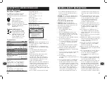
Страница 11: ... place and in working order 2 Remove adjusting keys and wrenches Form habit of checking to see that keys and adjusting wrenches are removed from the tool before turning it on 3 Keep work area clean Cluttered areas and benches invite accidents 4 Don t use in dangerous environment Don t use power tools in damp or wet locations or expose them to rain Keep work area well lighted 5 Keep children away A...

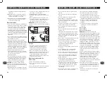
Страница 12: ... damaged or deformed saw blades Only use sharp blades When cutting round wood use clamps that prevent the workpiece from turning on both sides of the blade Never use your hands to remove sawdust chips or waste close by the saw blade Use only blades as recommended by the manufacturer Do not use blades manufactured from high speed Steel If the table insert is damaged or worn have it replaced by an a...

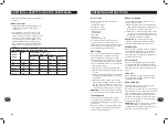
Страница 13: ...p of the saw arm pull on the release knob 6 rotate it 45 and let go slowly raise the saw arm WARNING Do not lift the saw whilst holding on to the guards Use the carrying handle 8 Transportation Lift the mitre saw only when the saw arm is locked in the down position the saw is switched off and the plug is removed from the power point Only lift the saw by the carrying handle 8 or outer castings Do n...

Страница 14: ...ves safety To turn on the laser lines press the laser light on off switch 2 To turn off the laser press the laser light on off switch 2 one more time OPERATING INSTRUCTIONS OPERATING INSTRUCTIONS Setting the table square with the blade 1 Make sure that the electrical plug is removed from the power point 2 Push the saw arm 5 down to its lowest position and engage the release knob 6 to hold the saw ...

Страница 15: ... blade OPERATING INSTRUCTIONS 6 When cutting long pieces of timber support the opposite end of the timber with the side support bars 37 a roller stand or a work surface that is level with the saw table 7 Use the clamp assembly 10 to secure the workpiece wherever possible 8 It is possible to remove the clamp assembly 10 by loosening the clamp assembly lock 11 and moving it to the other side of the ...

Страница 16: ... is not directed towards the eye of a person for longer than 0 25s Always ensure the laser beam is aimed at a sturdy workpiece without reflective surfaces Wood or rough coated surfaces are acceptable Bright shiny reflective surfaces are not suitable for laser use as the reflective surface could direct the beam back at the operator GUARANTEE Always remember to switch off the laser on off switch 2 a...

Страница 17: ......

Отзывы: