the clamping flange with the collar into the drive shaft and make sure that the
lug of the drive shaft engages into the groove of the clamping flange. Press the
drive shaft lock (18) and tighten the hexagon head bolt (10). Check the diamond
cutting discs for secure fit. Swing the drive unit back in. Trial run the power tool
with the newly fitted diamond cutting discs for at least one minute without load
before starting work. The position of the diamond cutting discs can be marked
on the contact plate (9) for accurate positioning of the slits.
CAUTION
Diamond cutting discs get very hot. Let them cool down before touching or
removing.
2.4. Setting the switch handle and holding handle
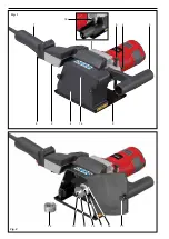
ROLLER’S Groove 125 (Fig. 1 and 2)
Pull out the mains plug. The switch handle (1) can be mounted parallel to the
machine axle and swivelled 90°. To do this, loosen the clamping screw of the
switch handle (2) and set the switch handle to the desired position, tighten the
switch handle clamping screw. The holding handle (3) can be mounted swivelled
in several detent positions. To do this, open the clamping screw of the holding
handle (4) until the teeth no longer engage. Move the holding handle into the
desired position (pay attention to positive lock of the teeth) and tighten with the
holding handle's clamping screw.
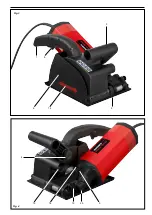
ROLLER’S Groove 180 SR (Fig. 3 and 4)
Pull out the mains plug. The holding handle (3) can be mounted swivelled in
several detent positions. To do this, open the clamping screw of the holding
handle (4) until the teeth no longer engage. Move the holding handle into the
desired position (pay attention to positive lock of the teeth) and tighten with the
holding handle's clamping screw (4). By removing the holding handle's clamping
screw (4) the holding handle (3) can be mounted turned 180°. Move the holding
handle into the desired position (pay attention to positive lock of the teeth) and
tighten with the holding handle's clamping screw (4).
2.5. Setting the depth stop
ROLLER’S Groove 125 (Fig. 1 and 2)
Pull out the mains plug. Undo
the holding handle's clamping screw (4) about
1 turn. To set the slitting depth, move the depth stop (5) to the desired position
and
tighten with the holding handle's clamping screw (4).
ROLLER’S Groove 180 SR (Fig. 3 and 4)
Pull out the mains plug. Undo the depth stop clamping screw (20) about ½ a
turn. To set the slitting depth, move the depth stop (5) to the desired position
and tighten with the depth stop clamping screw (20).
2.6. Dust extraction
WARNING
Inhalation of the dusts produced when slitting and cutting is harmful to the
health. Observe the national regulations. It is recommended to use a safety
vacuum cleaner/dust extractor of dust class M. Observe the operating instruc-
tions of the safety vacuum cleaner/dust extractor.
Push the suction nozzle adapter (16) onto the suction nozzle (15) on the
ROLLER’S Groove 125 so that the greatest possible distance of the pushed
on suction hose from the contact plate is achieved (Fig. 1).
No adapter is required for the suction nozzle on the ROLLER’S Groove 180
SR.
2.7. Fixing the workpiece
Workpieces which are slit or cut loosely must be rigidly fixed and secured
against being flung away.
2.8. Note on static
Before beginning work, make sure that the building static is not negatively
affected by the slitting or cutting work; consult the building management or a
static engineer if necessary. Slitting work in supporting walls may be subject
to national regulations. These regulations must be observed.
3. Operation
Use eye protection
Use a respirator
Use ear protection
Use hand protection
Suitable safety vacuum cleaners/dust extractors, a respirator and disposable
overalls must be used for work which could produce health hazardous dusts.
Observe the national regulations.
ROLLER’S Groove 125 and ROLLER’S Groove 180 SR are fitted with a safety
switch with lock (8). This enables the drive unit to be shut down at any time
and prevents unintentional staring of the drive unit. The safety switch with lock
must first be pushed in the direction of the mains lead and then pressed on the
ROLLER’S Groove 125. On the ROLLER’S Groove 180 SR first the locking
button on the side of the switch handle (1) and then the safety switch must be
pressed.
In order to simplify handling and to avoid damage, ROLLER’S Groove 125 and
ROLLER’S Groove 180 SR must be equipped with multi-function electronics
with electronic speed control or speed regulator. The multi-function electronics
perform the following functions:
●
Electronic start-up current limiting reduces the inrush current and therefore
allows operation on a 16 A fuse.
●
Soft start for protecting the drive unit and jolt-free starting after switching on.
●
Limiting of the idle speed to reduce noise and preserve the motor and gear.
●
Overload protection of the motor depending on the thrust pressure. The
motor current and thus the speed of the drive machine is reduced to a
minimum before overloading of the drive unit due to too high a thrust pres-
sure on the diamond cutting discs or blocking. However, the drive unit does
not switch off. If the thrust pressure is reduced, the speed of the drive unit
increases again. This process does not damage the drive unit even if it is
repeated several times. If the motor remains at standstill despite reducing
the thrust pressure, however, the drive unit must be switched off and the
diamond cutting discs may have to be re-engaged.
3.1. Slitting
ROLLER’S Groove 125
Use a suitable safety vacuum cleaner/dust extractor. Hold the ROLLER’S
Groove 125 by the switch handle (1) and holding handle (3) and set the contact
plate (9) against the surface to be machined. Make sure you have a safe footing
and enough room for the drive unit, safety vacuum cleaner/dust extractor,
suction hose and user. Safety vacuum cleaner/dust extractor. Switch on the
ROLLER’S Groove 125 at the switch handle.
To do this, first push the safety
switch with lock in the direction of the mains lead and then press it. When the
power tool has reached full speed, press the ROLLER’S Groove 125 onto the
surface with even thrust pressure. The diamond cutting discs penetrate the
surface. On reaching the slitting depth, push the ROLLER’S Groove 125 forward
against
the direction of the arrow (14) because otherwise the cutting disc could
lift uncontrolled out of the slit. Make sure that the diamond cutting discs do not
twist/jam. After finishing the slit, switch off the ROLLER’S Groove 125 and wait
until the diamond cutting discs have come to a complete standstill. Do not lift
off the surface until the drive unit is at a standstill. Switch off the safety vacuum
cleaner/dust extractor.
CAUTION
Diamond cutting discs get very hot. Let them cool down before touching or
removing.
Make sure that the suction hose of the industrial vacuum cleaner does not kink
and impair the dust extraction. Also make sure that no fragments of stone or
other objects jam in the suction nozzle (15) and/or suction hose. Empty the
dust bag of the safety vacuum cleaner/dust extractor early and clean/renew
the filter regularly. Observe the operating instructions of the safety vacuum
cleaner/dust extractor.
After slitting, a ridge remains between the slits. This can be broken out with a
slitting chisel (part no. 185024).
ROLLER’S Groove 180 SR
Use a suitable safety vacuum cleaner/dust extractor. Hold the ROLLER’S
Groove 180 SR by the switch handle (1) and holding handle (3) and set the
contact plate (9) against the surface to be machined. Make sure you have a
safe footing and enough room for the drive unit, safety vacuum cleaner/dust
extractor, suction hose and user. Safety vacuum cleaner/dust extractor. Switch
on the ROLLER’S Groove 180 SR at the switch handle. To do this, first press
the lock button on the side of the switch handle (1) and then press the safety
switch (8). When the power tool has reached full speed, press the ROLLER’S
Groove 180 SR onto the surface with even thrust pressure. The diamond cutting
discs penetrate the surface. On reaching the slitting depth, push the ROLLER’S
Groove 180 SR forward
in the direction
of the arrow (14) because otherwise
the cutting disc could lift uncontrolled out of the slit. Make sure that the diamond
cutting discs do not twist/jam. After finishing the slit, switch off the ROLLER’S
Groove 180 SR and wait until the diamond cutting discs have come to a complete
standstill. Do not lift off the surface until the drive unit is at a standstill. Switch
off the safety vacuum cleaner/dust extractor.
CAUTION
Diamond cutting discs get very hot. Let them cool down before touching or
removing.
Make sure that the suction hose of the industrial vacuum cleaner does not kink
and impair the dust extraction. Also make sure that no fragments of stone or
other objects jam in the suction nozzle (15) and/or suction hose. Empty the
dust bag of the safety vacuum cleaner/dust extractor early and clean/renew
the filter regularly. Observe the operating instructions of the safety vacuum
cleaner/dust extractor.
After slitting, a ridge remains between the slits. This can be broken out with a
slitting chisel (part no. 185024).
3.2. Cutting
ROLLER’S Groove 125
Use a suitable safety vacuum cleaner/dust extractor. Only insert one diamond
cutting disc in the machine. Secure/clamp the workpiece to be cut. Hold the
ROLLER’S Groove 125 by the switch handle (1) and holding handle (3) and
setthe contact plate (9) against the workpiece to be cut. Make sure you have
a safe footing and enough room for the drive unit, safety vacuum cleaner/dust
extractor, suction hose and user.. Safety vacuum cleaner/dust extractor. Switch
on the ROLLER’S Groove 125 at the switch handle. To do this, first push the
safety switch in the direction of the mains lead and then press it. On reaching
full speed, press the ROLLER’S Groove 125 against the workpiece with even
eng eng
Содержание Groove 125
Страница 2: ...Fig 2 10 13 11 12 Fig 1 1 2 3 4 5 6 14 9 8 15 7 12 17 16 18...
Страница 3: ...Fig 4 Fig 3 1 8 3 14 9 6 15 18 5 20 19 4...
Страница 55: ......

