Introduction
IEEE 802.11 (a/b/g)
15
Operating Manual 1171.5283.12 ─ 18
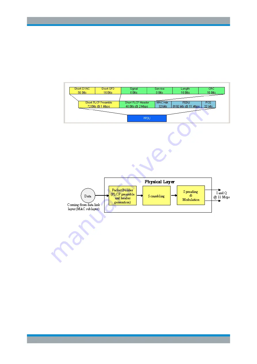
number of bits transmitted in the SYNC field is reduced from 128 to 56. In the short
header, however, the number of data bits transmitted remains unchanged, but the data
rate is doubled (to 2
Mbps). These measures halve the transmission periods of pream-
ble and header in the short PLCP format, as compared to the long PLCP format.
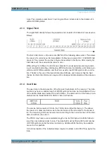
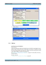
The frame structure can be seen in the figure below (also indicated in the "PPDU Con-
figuration" dialog):
2.3
Data Spreading and Modulation CCK-PBCC
The R&S
Signal Generator simulates signals in accordance with 802.11 on the physi-
cal layer. In the standard, the data link layer or, to be more precise, the MAC sublayer
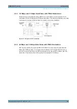
provides the input data for this layer The following graph illustrates the signal genera-
tion process.
Figure 2-1: Principle of 802.11b/g signal generation
Depending on the PLCP PPDU format used, the PLCP preamble and the PLCP
header are combined in the packet builder. The PSDU field of the packet is filled with
the input data of the physical layer block. In the next step, all the packet data is scram-
bled. The actual spreading and modulation of the data signal to the resulting chip rate
of 11
Mcps comes next.
However, the data rates and modulations of the individual fields of a packet can differ.
The PLCP preamble always has a data rate of 1
Mbps, and is DBPSK-modulated.
Besides the actual modulation, spreading to the resulting chip rate occurs.
The PLCP header is either treated exactly like the preamble (long PLCP PPDU for-
mat), or DQPSK-modulated at a data rate of 2
Mbps (short PLCP PPDU format). Data
rates (1
Mbps, 2
Mbps, 5.5
Mbps, 11
Mbps, etc) with different modulations can be used
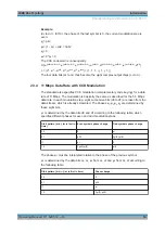
for the data part of the packet, the PLCP service data unit (PSDU). The following table
gives an overview of the different combinations of data rates, modulations and spread-
ing/coding methods.
Data Spreading and Modulation CCK-PBCC


