background image


55 

Robot Frame - Top View 1 


Fan  

On/Off Switch 

Battery strap 

Road Rage 

 Audio Amp 

MP3 Player 

RC Receiver

RC Receiver 

Antenna

Serial No./Model No. 

Sticker 

151 Voice Transmitter 

37 Pin Connection  

Wire to upper robot 

connects here. 

Voice Modifier

Battery Connector 

Voice Receiver 

Raise Antennas

Headlight/Body Light 

Connection and Fuse 

Audio Amp 

Master Volume 

Speaker Wire

Speaker Wire 

Содержание Vehicle Robot

Страница 1: ...i Vehicle Robot Operating Manual 1610 West 1600 South Springville UT 84663 Phone 801 489 4466 FAX 801 489 8241 Robotronics com Version 6 6 ...

Страница 2: ... read this manual carefully It will help you make the most of your robot Attention to maintenance and proper training will greatly prolong the life of your robot Train users to take care of the robot and keep the robot covered and indoors Most problems you encounter will be minor and the manual will provide an answer Please feel free to contact us if you have unanswered questions relating to opera...

Страница 3: ... MH R C Transmitter Battery Diagram 14 Adapter for Charging 14 Chapter 3 Voice System Overview 15 Location of Voice Units 15 Belt Transmitter 16 Robot Receiver 17 151 System Robot TX and Belt 151 Receiver 18 Voice System Troubleshooting 19 Mouth Operation 21 Operator s Voice Headset Transmitter and Receiver 22 Chapter 4 Audio Amplifier 23 Chapter 5 MP3 Player 24 Chapter 6 Cassette Tape Player Syst...

Страница 4: ...pendix B Robot Parts Identification 54 Robot Frame Top View 1 55 Robot Frame Top View 2 56 Main Electronics Box Panel 57 Vehicle Main Electronics Board 58 Led Functions on the Main Board 59 Vehicle Fuse Block Detail 60 Robot Frame Bottom View Motor Pulley Set Screws 61 Vehicle Top 1 Underside View 62 Vehicle Top 2 Underside View 63 Eyes Servo Board 64 Character Head Inside View 65 Character Top Un...

Страница 5: ...n the robot In no event shall ROBOTRONICS Inc be liable for any incidental or consequential damages in connection with or arising from the use of the robot this manual or any procedures herein The buyer is further responsible to ensure that proper and complete training is given to those operating the robot system as all aspects of such operation cannot be covered in a brief manual such as this If ...

Страница 6: ...lways available to help with your questions Again most problems are easily solved The robot design is very modular to make removal of a part of the robot very easy For example the main electronics box which houses most of the electronic circuitry can be removed from the frame of the robot If you do need technical help or replacement parts call our Service Dept We can usually ship them the followin...

Страница 7: ...nd robot Never operate the robot out of line of sight Make sure trims sliders on the RC are centered prior to turning on the RC and the robot Operating distance should never exceed 100 feet When moving the robot through crowds the robot should be operated slowly and smoothly without any sudden changes of direction Walls turns and other obstacles are hazards to be avoided Never leave the robot ON w...

Страница 8: ...he metal of the main electronics box or the metal of the drive base This will result in damage to electronic components especially inside the main electronics box 3 Attach the upper robot to the lower 1 Set the upper robot on the lower robot body 2 As you put the top on connect the 37 pin connector which is a round connector and wire bundle running from the upper robot to the lower robot When conn...

Страница 9: ... panel Push the switch up to turn the robot on On some robots there is a hinged rear door to access this switch Tip There is a hook on the RC that you can attach a neck strap to You can use a RC or camera type neck strap 5 Set the volumes Check that the volume of the voice and MP3 player are at the level that your want The volume for the robot s voice is can be adjusted on the UHF Wireless Receive...

Страница 10: ...f the robot 2 Turn off the robot 3 Finally turn off the Radio Control Transmitter 9 Charge the batteries again Connect the Robot battery to the charger and bring it back to a full charge before leaving the robot This battery should not be left with a partial charge The transmitter battery should be charged if it is low Before a storage period charge both batteries to a full charge All of the major...

Страница 11: ...latches CAUTION If the upper robot is not properly latched it could come off while moving the robot causing damage to the upper robot To strap the robot on the cart roll the robot on with the back wheels first The back wheels will drop in to the recesses Put the cart s wheels against a wall if necessary There are four eye bolts under the front and rear bumpers Attach the hooks from the cart to the...

Страница 12: ...wing basic subsystems A Radio Control System B Voice System C Cassette Tape Player D Siren E Robot Battery Systems F Drive Motors G Eyelids and Eyes Left and Right Following are explanations of each subsystem some operating instructions and trouble shooting hints where appropriate ...

Страница 13: ...t or left will cause the robot to turn to the right or left respectively Movement is fully proportional so any variation or combination of movement is possible The horizontal and vertical trim tabs to the left and below the joystick are for centering and should be typically left in the center The only time that you would need to move these trims is if the robot started moving slightly on its own I...

Страница 14: ... RC Receiver located in the robot Drive Drive Trim Eyes Head Power On Off Charge Siren Lights Beacon Tape or MP3 Player Option Squirt Flashing Lights Not used on all robots RC Frequency on crystal RC Frequency on back of RC RX Crystal Power Signal Wire Plugs in to B 8 ...

Страница 15: ...r or large space use 4 Forward Reverse Trim lever for right control stick Normal Center Neutrals the drive motors If the robot is moving slightly slide this a few clicks until robot stops moving 5 Left and right Trim lever for right control stick Normal Center Neutrals the drive motors If the robot is moving slightly slide this a few clicks until robot stops moving 6 Crystal Transmitter Crystal Ha...

Страница 16: ...sic onto If you have the MP3 player option then your switches will take on other functions when the MP3 mode switch is held on Two of the switches are for sound effects on the SD memory card The other two are for playing and selecting songs that you load on to the SD card You can also change the volume on the remote with the left joystick Battery Compartment View of Switches Switches must stay in ...

Страница 17: ...ttery or be aware of how much charge there is left in the battery If you have an extra battery you can change batteries and keep going To install the NI MH battery pack you need to take the battery cover off the RC Disconnect the RC battery and put the NI MH battery in its place NI MH RC Battery and Charger Specifications NI MH RC transmitter battery 9 6 Volts 1500mAH NI MH RC transmitter battery ...

Страница 18: ...ch should be off See the battery compartment picture below 2 Crystal bad 2 Replace transmitter and receiver crystal or send RC in for repair 3 Wire is not plugged in correctly to the receiver This is typically a red black white wire 3 Hitec Receiver has a channel labeled B 8 This is the correct position One or two functions on the robot not working 1 Typically not the RC unless a switch or wire is...

Страница 19: ...on adjust the earphone so that you can hear well and the mic so that the volume is good Note The operator s transmitter and receiver can be worn next to each other If you want you can use a belt pack The 151 Receiver antenna can be put out of view in your pocket Location of Voice Units Voice Transmitter Operator wears Voice Receiver On the main electronics box in the lower robot 151 Transmitter On...

Страница 20: ...t level adjust on the unit Frequency channel Located on the back of the transmitter Function of the LED When turning on the power switch with a fresh alkaline 9 Volt the battery light will blink on momentarily and go out This indicates that it is powering up and that the battery is good Because the light is a low battery indicator when the light is on constant this indicates the battery is too low...

Страница 21: ...ment as little as possible because adjusting it will affect the range Frequency label Located on the side of the receiver Function of the LEDs TX LED This indicates that you are receiving a signal from the transmitter On some units it is a single TX light On other units it may have an A or B that it will alternate between AF LED This light indicates that audio is going through the receiver It will...

Страница 22: ...l the feedback is gone Frequency label Located on the back of the receiver Function of LEDs When turning the volume knob on with a fresh alkaline battery the red light will blink on momentarily and go out This indicates that it is powering up and that the battery has enough charge on it As labeled the light is a low battery indicator When the light is on constant this indicates that the battery is...

Страница 23: ...e good in the operator s transmitter and in the 151 receiver Normally when you turn the 151 receiver on the low battery light should blink on and go off When turning on the power switch of the transmitter the light should blink on and go off If either of these lights stays on constant the 9 volt battery is too low and must be replaced 2 Check that the battery is in the correct polarity and confirm...

Страница 24: ...tter receiver and headset in 1 Low Battery LED on steady or no LED flash 1 Replace the 9 Volt battery 2 Battery posts not touching the metal clips in the operator s receiver 2 Bend out the metal clips Put foam under clips 3 Headset plug to 151 RX has a broken wire 3 Unscrew cover of plug and look for broken wire 4 Robot 151 transmitter not turned on 4 Turn on audio and power 5 Power plug to robot ...

Страница 25: ... based on a typical voice volume and the headset microphone being about 1 inch from the operator s mouth Adjustment The adjustment is preset at the factory and should not need any adjustment If an adjustment is necessary see the Main Circuit Board diagram in the Appendix for the location of it It is labeled Moving Mouth sensitivity When this pot is adjusted clockwise this makes the mouth more sens...

Страница 26: ...22 Operator s Voice Transmitter and Receiver Mic Plug 3 5mm 3 5mm Headphones Plug Headset style that comes with the robot ...

Страница 27: ...his switch position Set the level at about 2 00 If this is too high you will get some distortion Problem Cause Action Siren No audio 1 Audio fuse blown 2 Speaker wires are disconnected 1 Replace fuse See fuse block diagram 2 Re connect speaker wires One speaker not working 1 One channel of booster bad 2 Speaker wire broken or disconnected 3 Speaker bad 1 Replace booster 2 Connect or replace wire 3...

Страница 28: ...ll not play Play Music When you first turn on the robot the MP3 player will take a few seconds to start up before you can operate it To play a song hold the MP3 mode switch and push the play switch shown on the diagram below Tips After you move forward or back to a new track the music will start right when you release the switch When you scroll to the last track it will stop there If you want to g...

Страница 29: ...memory card back in the MP3 player Play Sound Effects If you want to play a sound effect hold the MP3 mode switch while you hit the sound effect you want See the diagram above You can play any of the sound effects snd1 snd2 snd3 or snd4 with the switch as shown If you add sound effects or songs to be played in the place of snd1 4 they must have the filename of snd1 snd2 snd3 snd4 to play in their ...

Страница 30: ...lat spots on the capstan roller Specifications Output Jack 3 5mm stereo Power Input DC 3V Center negative Troubleshooting Cassette Player Problem Cause Action Cassette Player No tape operation 1 Tape player not on tape mode or volume not turned up 1 Put mode select to tape and turn volume up 2 Play button not pushed 2 Must push play button before hitting the switch on the radio control 3 Bad Tape ...

Страница 31: ...To control the oscillating speed adjust the siren frequency trim pot in the siren circuit The siren mode select is set to the common siren for your robot If the siren mode select is changed the siren frequency will very likely need to be adjusted NOTE The volume and oscillation are preset at the factory and do not need to be adjusted unless you want a different volume level or oscillation speed Tr...

Страница 32: ...arger This will recharge the battery full in about 8 12 hours depending on how long you have operated the robot It will not overcharge the battery if left ON indefinitely It goes to a float charge mode once the battery is fully charged Taking Care of the Robot Battery The number one rule for battery care is to keep the batteries fully charged at all times Like all batteries there is some discharge...

Страница 33: ...the maximum 6 Amp rate of the charger stage 1 Red and green both on The battery is charging at the stage 2 rate of 1 5 to 5 Amps Green on Your battery is charged and ready to use It is now on float charge stage 3 Schumacher 3 Amp Battery Charger Status Indicating Lights Amber Charging Green Charged and is now in float charge Red Check battery The charge clips may be on wrong or the battery may be ...

Страница 34: ...he charger to rain 9 Replace defective cords and wires immediately 10 Do not operate this charger with a two bladed adapter plug or extension cord Doing so can result in serious personal injury 11 To reduce the risk of shock connect only to a properly grounded outlet 12 Remove personal metal items such as rings bracelets necklaces and watches when working near a lead acid battery If the Battery is...

Страница 35: ...eels off the ground Note Get the wheels off the ground to look at each wheel independently Neither drive operates Check both fuses in the fuse block Check set screws on the motor pulleys One drive motor does not operate either direction Set screw is loose on the motor pulley Tighten the Allen set screw s on the pulley on the motor shaft Drive motor is bad To test the motor for operation swap the m...

Страница 36: ...ster than the other at any given position of the joystick For example if at full speed the robot veers to the right this means that the left motor is going faster than the right motor To correct this you would adjust the forward drive adjust pot clockwise You may need to do some trial and error to get it just right It is best to use full speed during the adjusting because this will act as a good r...

Страница 37: ... and then tighten the setscrew When re positioning the head have the robot on so that the motor will maintain the motor center position The head motor is keeping the head position to the extreme left or right The in line connector to the blue feedback potentiometer has come disconnected Check if one of the wires has broken off the pot The feedback pot could have slipped The pot could be loose or t...

Страница 38: ...ervo motor with the problem The wire will run to the eye servo board If it is disconnected reconnect according to the eye servo board diagram If the servo does not work correctly wrong direction try one of the other outputs on the eye servo board See the diagram showing the eye servo board on the next page Bad servo Replace the servo motor One of the eyelids is at a different level than the other ...

Страница 39: ...his manual for correct placement on the circuit board Check the fuse on the fuse block The eyes work but not properly Check switches 3 and 4 in the battery compartment of the RC transmitter They should be in the normal blue position Put the joystick sliders in the middle 1 Left Eyelid 2 Left Eyelid Reverse 3 Right Eyelid 4 Right Eyelid Reverse 5 Eyes L R 6 Eyes L R Reverse 7 Mouth Servo 8 Red 5 V ...

Страница 40: ... back in Squirt Water Just hit the switch on the radio control to squirt This is a momentary spring loaded switch so that you can get short bursts of squirting If you have problems squirting but you hear the motor try cleaning out the nozzle in the front of the robot CAUTION The water squirter system should not be operated without water in it If you hear the motor but there is no water squirting c...

Страница 41: ...put balance between the direct sound and the effect sound Typically set this on EFX for the full effect 10 H R Key switch Not used 11 Pitch Switch Adjusts the amount of pitch shift 12 Mode Switch Selects the mode Typically use the pitch shifter mode The pedal on the pitch shifter is used to turn it on and off When the pitch shifter is on the power light labeled check will be lit The shifter will t...

Страница 42: ...box ever needs to be removed do not allow the shifter power wire plug to contact the metal box The metal box surface has a ground connection The fuse related to the shifter is the audio fuse located on the fuse block Below is a typical setting for the robot voice This will give you a shifted cartoon character or robot type voice If you do not want any change to your voice you can turn the balance ...

Страница 43: ...olates the signal from noise This board is the 5 Volt Isolation circuit board and is located off the back left corner of the main board Parts of the stop arm include the stop sign servo ball link rod spring servo arm and set screw To adjust the pull in tension and position of the arm loosen the set screw on the rod and increase or decrease the tension on the spring Description Part Description Par...

Страница 44: ...bracket servo arm rod ball links and set screw as shown in the diagram below To adjust the pull in tension and the out position of the arm loosen the set screw on the rod and move the position of the arm accordingly Make sure that the arm does pull in tightly against the bumper so that it does not move out at all when driving the robot Caution Do not move the robot when the crossing arm is in the ...

Страница 45: ...tward into the body to secure the upper robot to the lower If you have a typical vehicle robot two are in the middle left and right and two at the back To latch these you will need to reach in through the rear hatch or door If you have a character in the top two of the latches are located in the compartment where the Character sits The pins are to the left and right of the Character Reverse order ...

Страница 46: ...ive base back into the frame 1 Lift the back of the robot up enough to roll the drive base under and into position 2 Line up the 4 threaded studs with their holes and lower the robot onto them 3 You may need to put the electronics panel on now 4 Put the nuts back on which hold the metal drive base on to the frame Reverse steps for disassembly or assembly Removal of Main Box Remove 2 nuts lift plat...

Страница 47: ...eness and wear 7 Clean and lubricate mechanical parts of the robot such as the front wheel casters as needed with a light machine oil or LPS 1 Inspect the drive belt and pulley system making sure that the motor pulley set screws are tight You can use belt dressing on the drive belts if they are dry or squeaky 8 Wash the robot body with mild soap and water and a soft cloth and reattach the body Iso...

Страница 48: ...et and ratchet set Needle nose pliers Crimper Wire strippers Wire cutters diagonal cutters 7 16 3 8 wrenches Set of Allen wrenches Especially 3 32 and 1 8 sizes Short and long length sets Extra 9 Volt alkaline batteries Fine tip soldering iron and solder Solder wick and solder Small bottle of all purpose lubricant Digital Multimeter Volts Ohms 4 cable ties universal wire clips and wire tie downs ...

Страница 49: ...of specific ways to care for the fur Brush the fur regularly with a soft brush or white terry cloth towel to avoid matting over time This will help to keep it clean and looking fresh and new Be careful to be gentle excess friction may cause excess wear For regular cleaning maintenance use a damp soft cloth and warm water A drop or two of mild liquid detergent in the warm water before applying it w...

Страница 50: ...arrow masking tape to tape the line and then much larger tape and paper beyond that Method 2 More durable Note If you use method 2 you should contact a professional painter that has had experience painting on various types of surfaces These are automotive type paints and typically include a primer and base coat For a glossy look you can use a glossy base coat or a clear coat Brand Dupont Primer Ac...

Страница 51: ...ake sure that the glue is not running through the crack on to the outside of the body Note Avoid getting the glue on your hands by using latex or latex free gloves 5 Immediately put the fiberglass mesh or plastic piece on the glue and pat it down to saturate into the glue If you using an ABS plastic strip hold it on with a clamp 6 Apply some more PVC glue over the fiberglass mesh to saturate it so...

Страница 52: ...d top as per instructions in maintenance section If robot is stored with a dirty body it may be harder to clean at a later date as stains may become permanent 7 Storing your robot with a dust cover on it will keep the robot clean and protect the body from scratches It will also keep ultra violet light from affecting the ABS plastic body 8 The robot and batteries should be stored in a dry place bet...

Страница 53: ...49 APPENDIX A ...

Страница 54: ...and plug on to the main board 6 Headset plug to transmitter has a broken wire 6 Unscrew the cover of the male plug and look for broken wire or solder joint TEST Connect robot mic to transmitter If it now works problem is in headset Repair or replace Operator cannot talk 7 Still not working Call Robotronics Send transmitter receiver and headset in 1 Low Battery LED on steady or no LED flash 1 Repla...

Страница 55: ... on charger will not move 1 Battery has not been kept fully charged 1 Charge and discharge repeatedly Replace battery if it does not start charging 1 Both drive fuses blown 1 Replace drive fuses on fuse block Drive Motors Neither drive operates only To correctly evaluate drive problems look at wheels off the ground 2 Radio control drive section problem Contact Robtronics for help 1 Drive motor pul...

Страница 56: ...ye servo board 3 Find broken wire on red black or check fuse for eye servos on fuse block Check the 5 Volt Regulator on the main circuit board 1 In line fuse blown or fuse blown on the fuse block yellow wire 1 Replace the 5 Amp fuse which is in line on the wire Follow wire from water squirter switch Water Squirter Cannot fill reservoir 2 Broken wire at water squirter switch or coming from main box...

Страница 57: ...53 Robot Block Diagram ...

Страница 58: ...54 APPENDIX B ROBOT PARTS IDENTIFICATION ...

Страница 59: ...r RC Receiver RC Receiver Antenna Serial No Model No Sticker 151 Voice Transmitter 37 Pin Connection Wire to upper robot connects here Voice Modifier Battery Connector Voice Receiver Raise Antennas Headlight Body Light Connection and Fuse Audio Amp Master Volume Speaker Wire Speaker Wire ...

Страница 60: ...56 Robot Frame Top View Box Open Fuse Block See Fuse Block Detail Diagram for Fuse size and circuit Main Circuit Board Active Filter Water connections Water pump ...

Страница 61: ...57 Main Electronics Box Fuse Block See Fuse Block Detail Diagram for Fuse size and circuit Main Circuit Board Active Filter MP3 Player Option or Tape Player RC Receiver On Off Switch Battery Connection ...

Страница 62: ... Player and Tape Player Cass 3 Volts Switching Left Drive Circuit Right Drive Circuit Pwr to Voice Modifier and Voice RX Cassette 3V Power Siren Frequency Siren Volume Siren Mode Select Cassette Audio In 101 RX Audio In Out to Audio Amplifier Signal to Stop Arm Crossing Arm Option Drive Straightness Adjustments Forward Reverse Reds Flash Output 5 Reds Flash Output 6 Output 4 Yellows Flash Output 7...

Страница 63: ... signal present led is off Led 2 Moving mouth or flashing eye lights detection This flashes if there is audio coming through Led 3 Half way point of the audio detection Flashes when there is audio present Led Bank Used for looking at states of the processor outputs etc If these are on the processor is getting 5 V Stop Arm Steering Wheel Direction Jumper ...

Страница 64: ... Power to Character control board includes head turning mouth steering servo and eyes servos eye servo board Comes off the switched output fuse Audio 5 Amp Left Drive 20 Amp Super 15 Amp Standard Right Drive 20 Amp Super 15 Amp Standard 5 Volt Reg 3 Amp Processor and RC Receiver Switched Outputs 15 Amp 5 Volt Reg 3 Amp Eye Servo Board Stop Arm Servo Bus Red Wires 12 Volt Power Wires from Main On O...

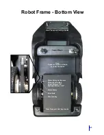
Страница 65: ...eakers will be in wheels or under the frame Motor Pulley Set Screws Allen wrench sizes Super Motors 1 8 Standard Motors 3 32 Motor Pulley Drive Belt Wheel Pulley Front Transport Cart Eye Hooks Caster Wheels Rear Transport Cart Eye Hooks ...

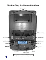
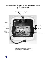
Страница 66: ... Servo Arm Eye Servo Board Opto shift board Right Body Latch Left Body Latch Rear Body Latches Eyelid Rod Eyelid Rod Left Eyelid Servo Eyes L R Servo Eye Plate Top Style 1 Robots Freddie Buster Andy Barney Toby Servo Arm Set Screw M2 5 x 45 x 8mm Phillips Pan Head Machine Screw ...

Страница 67: ...t Eyelid Servo Right Eyelid Servo 37 Pin Connector Servo Arm Servo Arm Eye Servo Board Opto shift board Left Body Latch Right Body Latch Eyelid Rod Eyelid Rod Eyes L R Servo Servo Arm Set Screw M2 5 x 45 x 8mm Phillips Pan Head Machine Screw ...

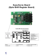
Страница 68: ...low Black Brown 1 Left Eyelid 2 Left Eyelid Reverse 3 Right Eyelid 4 Right Eyelid Reverse 5 Eyes L R 6 Eyes L R Reverse 7 Mouth Servo 8 Robot Typical Connection Location of Board in Robot Vehicle robot 2 3 6 7 In Upper robot 5 Pin Connector White Black Red 1 2 3 4 5 6 7 8 COPYRIGHT 1997 ROBOTRONICS 4015 ...

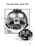
Страница 69: ...aracter Head Inside View Right Eyelid Servo Left Eyelid Servo Set Screw Set Screws In line connectors for each servo Mouth arm Servo Arm Eyelid Rod Eyes Left Right Servo Servo Mouth with Servo Arm Set Screw ...

Страница 70: ...Set Screw Steering Wheel Servo Head Turning Motor Head Turning Feedback Pot Body Latch Eyes Servo Board 37 Pin Connector Character Control Board Body Latch Steering Servo Connector See Character Board Diagram for detail of connections on the Character board ...

Страница 71: ...tor Servo Rod Body Latches 37 Pin Connector Character Control Board Servo Arm Set Screw Steering Wheel Servo Head Turning Motor Head Turning Feedback Pot Eyes Servo Board See Sparky Control Board Diagram for detail of connections on the Sparky board Body Latch Body Latch ...

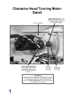
Страница 72: ...rn pot Tracks with movement of the head sending head position to processor Set Screw on Pot Shaft 3 32 Allen Set Screw on Motor Shaft 3 32 Allen Head Position To loosen the head and reset the head position there is an Allen set screw in the neck area Pull down the fur below the neck and there is a hole in the plastic to access the set screw Use a 3 16 Allen wrench for this The head has to be looki...

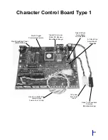
Страница 73: ...Pot wires Black red orange Head Turn Motor Wire Blue Yellow Fuse in line 1 5 Amp Mouth Trigger Purple jumper purple Signal From Lower Robot RC Receiver Blue Black Orange Mouth Switching Power Black Yellow Signal to Eyes Servo Board Yell Gray Blk 5 Volts to Eye Servo Board Black Red ...

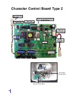
Страница 74: ...m Lower Robot RC Receiver Blue Black Orange Signal to Eye Servo Board Yellow Grey Black 5 Volts to Eye Servo Board Black Red Head Turn Feedback 12v Power from Lower Robot Head Turn Motor Wire Blue Yellow Character Control Board Type 2 Character Control Board Servo Board Eyes and Mouth ...

Страница 75: ...Cruiser and McGruff Cruiser it is just below the windshield on the right hand side On other robots open the rear door and it is on the back right side of the eye plate To change the pattern To cycle forward to the next pattern push the button for less than 1 second and release To cycle back to the previous pattern push the button for more than 1 second and release If you keep going forward you wil...

Страница 76: ...ights Flashing Grey Eyes Signal Black Eyes Signal Black Eyes Gnd 5V Red Eyes Power 5V Yellow Eyes Signal Yellow Lights Flashing Yellow Lights Flashing Red Steering Servo Black Steering Servo Red Chest Board Power Black Chest Board Ground White Steering Servo Observe pin numbers not orientation Can be used for the upper robot and panel side This view is for Upper robot 37 Pin Red flashing is for An...

Страница 77: ...73 APPENDIX C CHECKLIST AND MAINTENANCE FORMS ...

Страница 78: ...Radio Control is in good condition Antenna is attached to it Headset and accessories are in good condition Install new 9 Volt alkaline batteries in the voice receiver and voice transmitter Battery chargers are in good condition There should be one for the robot battery and one for the radio control Robot moves forward back and left right with no problems The head turns left and right robots with c...

Страница 79: ...75 ...

Страница 80: ...76 Notes ...

Страница 81: ...77 Technical Tips ...

Отзывы: