


35
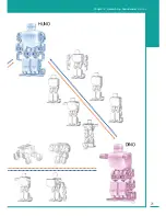
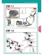
Chapter 2. Assembling RoboBuilder
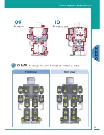
Right Arm
Head
Left Arm
Right Leg
Left Leg
ID 11
ID 14
ID 12
ID 15
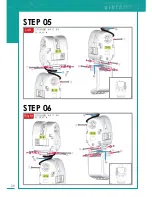
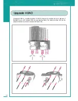
STEP 19
With the control box half slid
down, insert the cables from
both legs to the connectors on
the control box before the con-
trol box is fully pushed down
and secured. All cables, other
than the sensor cable from the
head, can be plugged into any
of the connectors.
STEP 20
①
: Power ON
②
: Check PF1
Blue LED
③
: Check the basic
posture (
)
※ If battery is not sufficiently charged, connect
the power adapter to run the robot.
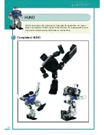
H
U
N
O
Содержание DIY Robot kit
Страница 2: ......
Страница 20: ...21 Chapter 2 Assembling RoboBuilder HUNO DINO ...
Страница 36: ...37 Chapter 2 Assembling RoboBuilder H U N O ...
Страница 49: ...50 STEP 18 STEP 17 B40 ID 01 ID 06 ID 11 ID 12 ID 02 ID 07 ...
Страница 108: ...109 Chapter 4 Troubleshooting MEMO ...
Страница 109: ...110 MEMO ...