


IMR01H01-E4
7
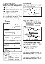
5.2 PV/SV Monitor Mode
PV/SV monitor mode can confirm the measured value (PV) and the set value (SV). Usually, set to this mode during control execution.
For checking the measured value (PV) and set value (SV) during operation, the following two methods are available.
!"
Checking PV and SV corresponding to each channel
In PV/SV monitor mode, the PV and SV corresponding to the displayed channel can be checked. Each time the CH key is pressed, the
SV corresponding to each channel within the memory area (hereinafter called “control area”) used for control can be checked for each
channel.
Display example:
When the
setting change rate limiter is set, a condition in which the set value (SV) goes changing according to that rate of
change is displayed.
If the instrument needs to be switched to RUN or STOP mode, press the <RS key in PV/SV monitor mode. In addition,
RUN/STOP can be selected by key operation or by open or closed contact input (option).
6.3 Transfer of RUN/STOP (P. 14)
!"
Checking SV corresponding to all of the channels within the control area
The SV corresponding to all the channels within the control area are automatically checked at each scan interval time.
5.4 Setup Setting Mode (P. 8), 7.5 Scan Display Function (P. 16)
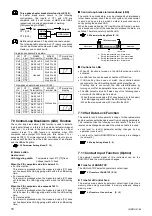
5.3 SV Setting & CT Monitor Mode
SV setting & CT monitor mode is used to set the set value (SV) and control area or to monitor the current value (current transformer 1,
current transformer 2).
Press the SET key with state of PV/SV monitor mode to shift to this mode. The UP, DOWN or <R/S key is used to
change the numeric value, and the SET key is used to change the parameter as well as to register the numeric value.
!"
Description of each parameter
Set value (SV) setting
Set the set value (SV) which is the desired value for control.
Setting range:
Within input range
Factory set value: Temperature input 0
°
C [
°
F] or 0.0
°
C [
°
F]
Voltage input 0.0 %
•
Up to eight memories per channel can be set with one set value (SV) assumed to be one
memory.
•
The set values (SV) corresponding to all of the channels within the same control area can be
simultaneously set as the same value.
•
No setting can be changed when “1 (Lock)” is selected by the lock level 1.
Memory area transfer
Selects the memory area used for control (Hereafter called the control area).
Setting range:
1 to 8
Factory set value: 1
•
No setting can be changed when “1 (Lock)” is selected by the lock level 2.
•
One set value (SV) and up to eight setting items of the parameter setting mode per channel
can be stored.
For details of the setting items of parameter setting mode, see
5.5 Parameter Setting
Mode. (P. 10)
Current transformer 1 monitor
Displays the input value of the current transformer 1 used when the instrument is provided with the
heater break alarm 1.
Display range:
0.0 to 100.0 A
•
Not displayed when this instrument is not provided with the heater break alarm 1 function.
•
Displays the input value of the current transformer 1
used when the instrument is provided with
the heater break alarm 2 (Z-168).
Current transformer 2 monitor
[ Correspond to only MA900]
Displays the input value of the current transformer 2 used when the instrument is provided with the
heater break alarm 2 (Z-168).
Display range:
0.0 to 100.0 A
•
Not displayed when this instrument is not provided with the heater break alarm 2 function.
•
In case of MA901, this monitoring screen is not provided.
To PV/SV monitor mode
PV/SV monitor mode display
PV
CH
SV
AREA
PV
CH
SV
AREA
(Option)
(Option)
PV
CH
SV
AREA
PV
CH
SV
AREA
PV
CH
SV
AREA
Indicates that PV corresponding to channel 1
within the control area is 300
°
C
Indicates that PV corresponding to channel 1
within the control area is 350
°
C.
Indicates that PV/SV now on display
corresponds to channel 1 within control
area 1.
Indicates that memory area number 1 is
selected as a control area.