RKC INSTRUMENT MA900 Series Скачать руководство пользователя страница 16

IMR01H01-E4

16

7. FUNCTIONS

This chapter describes an outline of function of MA900/MA901.

7.1 PV Bias Function

The value set in the PV bias is added to the input value (actual
measured value) to correct the input value. The PV bias is used
to correct the individual variations in the sensors or when there
is difference between the measured values (PV) of other
instruments.

5.4 Setup Setting Mode (P. 8)

7.2 Digital Filter Function

This is a software filter which reduces input value variations
caused by noise. If the time constant of this filter is set
appropriately to match the characteristics of the controlled
object and the noise level, the effects of input noise can be
suppressed. However, if the time constant is too small, the filter
may not be effective, while if the time constant is too large, then
the input response may actually deteriorate.

5.4 Setup Setting Mode (P. 8)

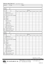
7.3 Multi-Memory Area Function

This function is to store the parameters such as temperature set
value (SV), etc. in up to 8 memories. The parameters which can
be stored as one of memories are set value (SV), alarm 1, alarm
2, alarm 3, proportional band, integral time, derivative time, anti-
reset windup, cool-side proportional band, overlap/deadband,
setting change rate limiter and use/unused of channels. The
parameters stored in one of 8 memories retrieved at necessity
and used for control. The memory area used for this control is
called the control area.

5.3 SV Setting & CT Monitor Mode (P. 7),
5.5 Parameter Setting Mode (P. 10)


Memory area 

Control area 

                Parameter           

CH1  CH2 

CH3 

CH4 

Set value (SV)


Control loop break alarm


Control loop break alarm deadband


Alarm 

Alarm

 2 

Alarm

 3 

Proportional band


Integral time


Derivative time


Anti-reset windup


Cool-side proportional band *


Overlap/deadband *


Setting change rate limiter


Use/unused of channels


These setting items can not be set in MA901. 

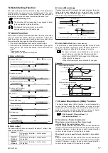
7.4 Setting Change Rate Limiter Function

The setting change rate limiter functions so as to change the set
value (SV) gradually toward the set value after being changed.
This limiter sets how much the set value is changed upward or
downward per minute.

5.5 Parameter Setting Mode (P. 10)

Example:

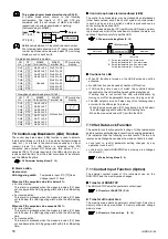
7.5 Scan Display Function

The scan display function is for automatically selecting the
PV/SV monitor at the scan interval time for the measured values
(PV) and set values (SV) corresponding to all of the channels
within the control area. This function enables the control trend of
each channel to be checked.

• 

The transfer speed of the scan display is set with the interval
time of setup setting mode (P. 9).

• 

Use the CH key to stop or start of the scan display function.
The CH key operation is as follows.

Press the CH key for 2 sec

Scan start.

Press the CH key

Scan stop.

The channel number can be
changed like 1

2

3

4

1

・・・

during scan stopping.*

* In case of MA901:
  1

2

3

4

5

6

7

8

1

・・・

• 

During display scanning, each unused channel is skipped.
The unused channel means the channel set to 

oFF

 in

used/unused channels of the parameter setting mode.

• 

When the channel number is manually changed, both PV and
SV corresponding to any unused channel are also scan-
displayed.

• 

The scan display can be made even at any of RUN and STOP.

Scanning display examples:

When scanning PV/SV corresponding to channel 1 to channel 4
in the control area 1 at 2 seconds intervals:

When scanning PV/SV corresponding to channel 1 to channel 4
(channel 3: unused channel) in the control area 1 at 2 seconds
intervals:

PV

CH

SV

AREA

PV

CH

SV

AREA

PV

CH

SV

AREA

PV

CH

SV

AREA

PV

CH

SV

AREA

PV

CH

SV

AREA

<Increasing set value to higher value>

Increase
gradually

Change set value at
this point

SV

SV

[After change]

Time

SV

[Before change]

<Decreasing set value to lower value>

Decrease
gradually

Time

SV

SV

[Before change]

SV

[After change]

Change set value at
this point

PV

CH

SV

AREA

Press the CH
key for 2 sec.

2 sec

2 sec

2 sec

Press the CH
key for 2 sec.

2 sec

2 sec

Содержание MA900 Series

Страница 1: ...to avoid electric shock by operating personnel All precautions described in this manual should be taken to avoid damage to the instrument or equipment All wiring must be in accordance with local codes and regulations All wiring must be completed before power is turned on to prevent electric shock instrument failure or incorrect action The power must be turned off before repairing work for input br...

Страница 2: ...arm G Deviation high low alarm 4 W SV low alarm H Process high alarm 8 Alarm 2 option 3 N No alarm J Process low alarm A Deviation high alarm K Process high alarm 4 B Deviation low alarm L Process low alarm 4 C Deviation high low alarm M FAIL alarm D Band alarm P Heater break alarm CTL6P 5 6 E Deviation high alarm 4 S Heater break alarm CTL12 5 6 F Deviation low alarm 4 V SV high alarm G Deviation...

Страница 3: ...8 1 91 8 Mounting bracket 96 96 Unit mm Rubber option Up to 4 mounting brackets can be used Panel cutout For mounting of the MA900 MA901 panel thickness must be between 1 to 10 mm When mounting multiple MA900 MA901s close together the panel strength should be checked to ensure proper support If the MA900 MA901s have waterproof dustproof options protection will be compromised and not meet IP65 by c...

Страница 4: ...size M3 6 Recommended tightening torque 0 4 N m 4 kgf cm 3 2 Terminal Configuration MA900 9 Input 3 4 RTD RTD1 B B A 15 14 13 RTD2 B B A 18 17 16 RTD3 B B A 21 20 19 RTD4 B B A 24 23 22 Thermocouple TC1 15 14 TC2 18 17 TC3 21 20 TC4 24 23 Voltage 15 14 IN1 18 17 IN2 21 20 IN3 24 23 IN4 1 Power Option 6 Contact input RUN STOP Memory area transfer 40 39 DI2 DI1 DI4 42 41 43 DI SET 5 Alarm output Rel...

Страница 5: ...8 59 60 1 2 3 4 5 6 7 8 9 10 11 12 1 2 3 1 2 3 5 4 6 7 10 9 With communication or contact input function 5 10 9 8 4 3 RTD and voltage inputs Not isolated between each input channel With heater break alarm function 1 Not isolated between each channel 2 Relationship between CT input and channel number see 7 8 Heater Break Alarm HBA Function P 18 4 PARTS DESCRIPTION This chapter describes various dis...

Страница 6: ...channels SET key SET key SET key SET key SET key SET key SET key SET key SET key SET key SET key SET key SET key LbA Lbd AL1 AL2 AL3 P I d Ar Pc db SVrL CH E SV Setting CT Monitor Mode P 7 To PV SV monitor mode SET key Set value SV setting Memory area transfer Current transformer 1 monitor Current transformer 2 monitor SET key SET key SET key SV ArE CT1 CT2 Press the R S key while pressing the SET...

Страница 7: ...ge Factory set value Temperature input 0 C F or 0 0 C F Voltage input 0 0 Up to eight memories per channel can be set with one set value SV assumed to be one memory The set values SV corresponding to all of the channels within the same control area can be simultaneously set as the same value No setting can be changed when 1 Lock is selected by the lock level 1 Memory area transfer Selects the memo...

Страница 8: ...eferring to monitor value from the current transformer 2 Used only for three phase Displayed only for when the heater break alarm Z 168 is selected as alarm 2 Setting range 0 0 to 100 0 A OFF HBA2 function OFF Factory set value OFF No setting can be changed when 1 Lock is selected by the lock level 1 HBA is not available on a current output Set HBA2 set value to a value about 85 of current transfo...

Страница 9: ...an be changed when 1 Lock is selected by the lock level 1 Only the relevant parameter corresponding to the cannel set to MonI or ConT in used unused channels of the parameter setting mode can be scan displayed Lock level 1 Set to the control area now in operation to restrict parameter setting changes by the key operation Setting range 1 Items other than SV and alarms ALM1 to ALM3 0 Unlock 1 Lock 2...

Страница 10: ...99 digits Factory set value Temperature input 50 C F or 50 0 C F Voltage input 5 0 No setting can be changed when 1 Lock is selected by the lock level 1 Not displayed when FAIL alarm or control loop break alarm is selected for alarm 1 Alarm 2 ALM2 Set the ALM2 set value Displayed when any one of the deviation process and SV alarms is selected as the alarm 2 Setting range Process alarm SV alarm Sam...

Страница 11: ...he lock level 1 In case of MA901 this setting item is not provided Minus setting results in overlap Setting change rate limiter Set the amount of set value SV change per 1 minute when the SV is changed Setting range 0 0 1 to span min OFF Setting change rate limiter OFF Factory set value OFF No setting can be changed when 1 Lock is selected by the lock level 1 The set value SV while the setting cha...

Страница 12: ...2 Press the DOWN key three times to change to 1 The display changes to 100 When another area set value SV is changed without changing control area When changing the set value SV corresponding to channel 2 in memory area 3 from 150 C to 100 C with the memory area set to memory area 1 1 Press the SET key in PV SV monitor mode state to transfer to SV setting CT monitor mode 2 Press the R S key to lig...

Страница 13: ...ory area transfer The set values SV in other memory areas are simultaneously set to the same value without changing the control area When changing the set values SV corresponding to all of the channels in memory area 2 from 0 C to 300 C with the control area corresponding to memory area 1 1 Press the SET key in PV SV monitor mode state to transfer to SV setting CT monitor mode 2 Press the CH key D...

Страница 14: ...n RUN STOP RUN RUN STOP with Key Operation STOP is not displayed dSTP STOP STOP STOP KSTP SToP After the contact is closed it takes a short time until the action of this device is actually selected Therefore pay attention to this delay time if the device is used together with a sequencer etc 0 5 seconds shortest Only SToP is displayed at the time of STOP in the state without RUN STOP transfer by c...

Страница 15: ...otuning AT The AT function automatically measures computes and sets the optimum PID and LBA constants If the AT function is activated the optimum PID constants concerning the set value SV in the control area and the LBA setting time can be automatically set Limit cycle system is adopted This function is activated power ON during temperature rise and or when control is stabilized from any process s...

Страница 16: ...g items can not be set in MA901 7 4 Setting Change Rate Limiter Function The setting change rate limiter functions so as to change the set value SV gradually toward the set value after being changed This limiter sets how much the set value is changed upward or downward per minute 5 5 Parameter Setting Mode P 10 Example 7 5 Scan Display Function The scan display function is for automatically select...

Страница 17: ... alarm set value the alarm relay contact may repeatedly turn on and off due to input fluctuations By the differential gap repeated turning ON and OFF of the relay contact can be prevented Alarm differential gap Temperature input 2 2 0 C F Voltage input 2 0 Low alarm Low High OFF ON Differential gap Low alarm set value SV High alarm Low High OFF ON High alarm set value SV Differential gap Alarm hol...

Страница 18: ...ering width within the LBA setting time For reverse action This alarm is produced when the measured value PV does not rise beyond the LBA triggering width within the LBA setting time Control loop break alarm deadband LBD The control loop break alarm may be produced by disturbances other heat sources even if the control system is not abnormal In such a case an area in which no alarm is produced can...

Страница 19: ...tric shock always turn off the power before replacing the sensor WARNING Flashing Flashing PV display Input range Effective input range Input range α α The range to be displayed differ depending on the input type or the setting limit α PV flashing display PV display unit Overscale Underscale α PV flashing display 9 REMOVING THE INTERNAL ASSEMBLY Usually this instrument is not necessary to remove t...

Страница 20: ...00 times Data storage period Approx 10 years Alarm function Number of points 3 points Option 2 points Alarm type Specify when ordering Deviation high alarm FAIL alarm Deviation low alarm Deviation high alarm with hold action Deviation high low alarm Deviation low alarm with hold action Band alarm Deviation high low alarm with hold action Process high alarm Process high alarm with hold action Proce...

Страница 21: ...F N A5 199 9 to 400 0 C 1 2 T 01 T 199 9 to 100 0 C 1 2 T 02 100 0 to 200 0 C T 03 Thermocouple input and RTD input Type Range Code 0 0 to 350 0 C T 04 199 9 to 752 0 F 1 2 T A1 T 100 0 to 200 0 F 2 T A2 100 0 to 400 0 F T A3 0 0 to 450 0 F T A4 0 0 to 752 0 F T A5 W5Re 0 to 2000 C W 01 W26Re 0 to 2320 C W 02 0 to 4000 F W A1 0 to 1300 C A 01 0 to 1390 C A 02 PL II 0 to 1200 C A 03 0 to 2400 F A A...

Страница 22: ...nels Memory area No CH1 CH2 CH3 CH4 CH5 CH6 CH7 CH8 Set value SV Control loop break alarm Control loop break alarm deadband Alarm 1 Alarm 2 Alarm 3 Proportional band Integral time Derivative time Anti reset windup Cool side proportional band Overlap deadband Setting changing rate limiter Used unused of channels Item Display Set value RKC INSTRUMENT INC HEADQUARTERS 16 6 KUGAHARA 5 CHOME OHTA KU TO...

Отзывы: