


IMR01H01-E4
17
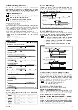
7.6 Batch Setting Function
The batch setting function enables the setting of the parameters
selected within one memory area simultaneously to the same
value for all of the channels. The set values (SV) as well as the
parameters set for each channel can be simultaneously set.
5.6.2 Batch setting (P. 13)
The set value (SV) corresponding to any unused channel
is also subjected to the batch setting.
All channels of all memory area can not be
simultaneously set as the same value.
7.7 Alarm Function
Alarm function sets up the alarm state when the measured value
(PV) or the deviation reaches the alarm set values. In the alarm
state, the alarm output is output, and the alarms are used to drive
the equipment danger signals or the safety equipment.
•
The output specifications are the relay contact output.
•
The alarm output condition can be determined by the type of
alarm action
1
, the output destination
1
and each alarm set
value
2
.
1
Specify when ordering
2
Setting item of the parameter setting mode
"#
Alarm action type
OFF
*
(Alarm status where the alarm set value is set to plus)
Low
High
Deviation high alarm
OFF
ON
Low
High
*
(Alarm status where the alarm set value is set to minus)
ON
*
(Alarm status where the alarm set value is set to plus)
Deviation low alarm
OFF
ON
Low
High
*
(Alarm status where the alarm set value is set to minus)
OFF
ON
Low
High
Deviation high/low alarm
OFF
ON
ON
Low
High
Band alarm
OFF
OFF
ON
Low
High
Process high alarm
OFF
ON
Low
High
Process low alarm
ON
Low
High
OFF
SV low alarm
ON
Low
High
OFF
SV high alarm
OFF
ON
Low
High
( : SV : Alarm set value)
"#
Alarm output
The alarm output (factory set value) of the alarm 1, alarm 2 and
alarm 3 are as follows.
Alarm 1
OR
output of the alarm 1 in all channels
(Energized)
Alarm 2
(Option)
OR
output of the alarm 2 in all channels
(Energized)
Alarm 3
(Option)
OR
output of the alarm 3 in all channels
(Energized)
"#
Alarm
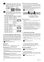
differential gap
If measured value (PV) is close to the alarm set value, the alarm
relay contact may repeatedly turn on and off due to input
fluctuations. By the differential gap, repeated turning ON and
OFF of the relay contact can be prevented.
Alarm differential gap: Temperature input 2 (2.0)
°
C [
°
F]
Voltage input 2.0 %
Low alarm
Low
High
OFF
ON
Differential gap
Low alarm set value
SV
High alarm
Low
High
OFF
ON
High alarm set value
SV
Differential gap
"#
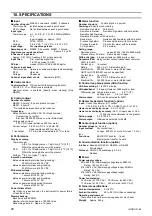
Alarm
hold action
(Specify when ordering)
This hold action is used to make alarm invalid until the PV exits
once from the alarm region by ignoring the alarm state even if
the PV is in the alarm state when the power is turned on.
The alarm hold action is activated when not only the
power is turned on, but also the following conditions
•
When the RUN/STOP is changed to the RUN mode
•
When the SV is changed
•
When the memory area (control area) is changed
Example:
W ith alarm hold action
W ithout alarm hold action
Alarm hold area
Time
Deviation
Measured value (PV)
PV
Alarm set value
SV
OFF ON
Time
PV
SV
OFF ON
ON
Alarm status
Alarm set value
Alarm status
Deviation
Measured value (PV)
7.8 Heater Break Alarm (HBA) Function
The heater break alarm (HBA) function is used to detect the
current flowing through the load (heater) by using a current
transformer (CT), to compare the current thus detected to the
heater break alarm set value, and thus to produce a heater
break alarm when any of the following causes occurs.
5.3 SV Setting & CT Monitor Mode (P. 7),
5.4 Setup Setting Mode (P. 8)
"#
Occurrence of heater break alarm
When heater current does not flow (Heater break,
malfunction of the control device, etc.):
Alarm is issued when the input value of the current transformer
is below the heater break alarm set value with the control output
turned on. However, no alarm may be normally issued when the
control output is turned on for less than 2 seconds.
When heater current goes following (welded relay contact,
etc.):
Alarm is issued when the input value of the current transformer
is above the heater break alarm set value with the control output
turned off. However, no alarm may be normally issued when the
control output is turned off for less than 2 seconds.