background image

Replacing SteelConnect SDI-2030 and SDI-5030 Gateway Components  | 35


 Installing or replacing network interface cards (NICs)

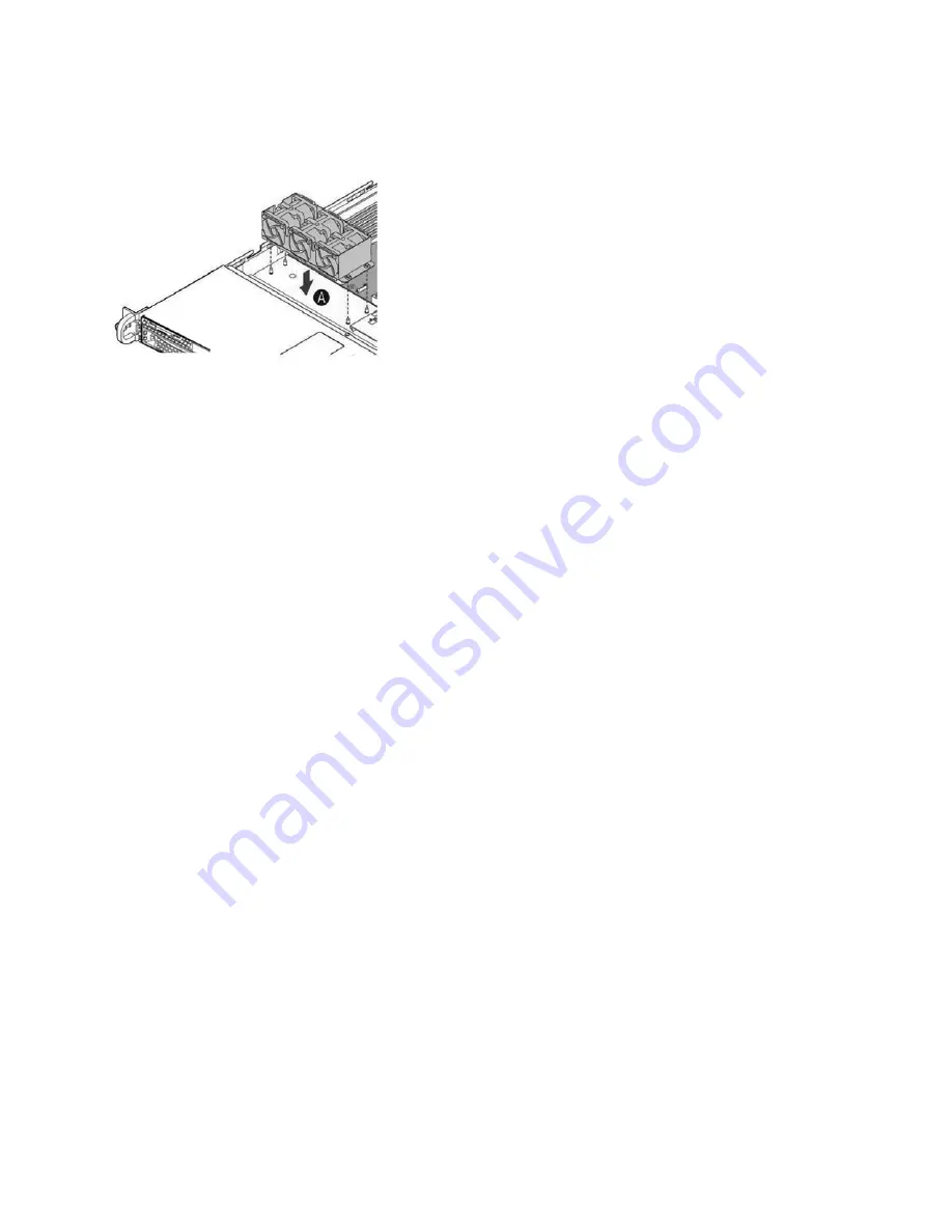
5. Align the fan assembly mounting holes with pins on the chassis base and push down until it is firmly 

seated. 

Figure 3-19. Installing the fan assembly

6. Attach the fan cable to the fan connector on the server board. 

7. Replace the chassis cover.

Installing or replacing network interface cards (NICs)

In the SDI-5030 and SDI-2030 gateways, PCIe riser-card slot 1 is open for configuration with any of the 
supported NICs. For details on supported NICs, see 

Appendix A, “Supported SDI-2030 and SDI-5030 

Gateway NICs.”


To install or replace a NIC

1. Power down the gateway and remove the power-supply cord.

2. Remove the cables connected to the gateway. 

3. Remove the gateway from the mounting rack, if necessary.

Содержание SteelConnect SDI-2030

Страница 1: ...SteelConnect Gateway Hardware Installation Guide Models SDI 2030 SDI 5030 August 2018...

Страница 2: ...trademarks of VMware Inc in the United States and in other countries This product includes Windows Azure Linux Agent developed by the Microsoft Corporation http www microsoft com Copyright 2017 Micros...

Страница 3: ...elConnect SDI 2030 and SDI 5030 Gateways 13 Site preparations or considerations 13 Site requirements 13 Safety information 13 Environmental considerations 14 Required tools and equipment 14 Rack mount...

Страница 4: ...Copper card 40 Four Port 10 GbE Copper card 41 Four Port 1 GbE Fiber Copper SFP card 41 Two Port 10 GbE Fiber SFP card 42 Four Port 10 GbE Fiber SFP card 43 B SteelConnect SDI 2030 and SDI 5030 Gatewa...

Страница 5: ...iverbed Knowledge Base log in to the Riverbed Support site at https support riverbed com Convention Meaning italics Within text new terms and emphasized words appear in italic typeface boldface Within...

Страница 6: ...ort Problems installing using or replacing Riverbed products Contact Riverbed Support or your channel partner who provides support To contact Riverbed Support open a trouble ticket by calling 1 888 RV...

Страница 7: ...1U gateway targeted for small enterprise deployments where the SDI 5030 gateway is too large The SDI 2030 gateway can also serve as a branch office appliance that has high throughput requirements The...

Страница 8: ...sed for video connectivity Serial RJ45 access port for communication input and output USB Three stacked ports that are 2 0 and 3 0 compatible Ports 1 to 4 SDI 5030 Preinstalled with Four Port 1 GbE Co...

Страница 9: ...e system ID LED is on the back of the gateway to the left of the video port NMI button recessed tool required for use Puts the gateway in a halt state and issues a nonmaskable interrupt NMI This state...

Страница 10: ...drive activity LED Activity blinking green NIC 2 activity LED port 5 activity LED Maps to port 5 on the rear panel Link green Activity blinking green The blink rate is consistent with the amount of ne...

Страница 11: ...t only 12 VSB or power supply in cold redundant state Amber Power supply critical event causing a shutdown failure OCP OVP fan fail 1 Hz blinking amber Power supply warning possible high temperature h...

Страница 12: ...12 SteelConnect SDI 2030 and SDI 5030 Gateway Overview SteelConnect SDI 2030 and SDI 5030 gateway LEDs...

Страница 13: ...on page 13 Environmental considerations on page 14 Site requirements A standard electronic environment where the ambient temperature doesn t exceed 95 F 35 C and the relative humidity doesn t exceed 9...

Страница 14: ...circulation to maintain proper operating temperatures Never cover or obstruct the gateway ventilation slots Do not position the gateway near high powered radio transmitters or electrical equipment su...

Страница 15: ...RMK 1 VRAIL kit that ships with the gateway includes a ball retainer lock on the outer member The lock provides better lock functionality when the inner member is extended The rail kit also has an in...

Страница 16: ...eelConnect SDI 2030 and SDI 5030 gateways The RMK 1 VRAIL has the components shown in Figure 2 1 Figure 2 1 Slide rail components Figure 2 2 Ball retainer lock for the RMK 1 VRAIL kit A Front bracket...

Страница 17: ...s to the appropriate vertical position on the rack and insert the fasteners Move the ball retainer to the front of the slide rails See Figure 2 3 Figure 2 3 Installing the rails to the rack 2 Install...

Страница 18: ...button in the inner member to release the lock and allow the gateway to close See Figure 2 5 Figure 2 5 Installing the gateway to fixed slides bezel attached To remove the gateway 1 Fully extend the s...

Страница 19: ...1 PRAIL kit Note The RMK 1 PRAIL kit does not require the use of tools however there is an option to use a screw on each rail for added stability 1 Install the rails to the rack posts Insert the rail...

Страница 20: ...gure 2 9 Figure 2 9 Extending the slides 3 Position the gateway so that the keyed openings on the rails are aligned with the locating pins on the sides of the gateway See Figure 2 10 Figure 2 10 Align...

Страница 21: ...e gateway out of the rails and remove the gateway from the rack Powering on the gateway This section describes how to connect the AC power and power on the gateway Caution In European electrical envir...

Страница 22: ...hroughput For the SDI 2030 gateway located at the branch upon bootstrap port 1 reserved for high availability HA and all the remaining ports are used as uplinks After the appliance establishes communi...

Страница 23: ...ncludes the following sections Field replaceable units on page 24 Required tools on page 24 Removing and installing the bezel on page 25 Removing and installing the chassis cover on page 26 Removing a...

Страница 24: ...by a certified service technician only Your warranty does not cover damage due to servicing that is not authorized by Riverbed Read and follow the safety instructions in the Safety and Compliance Guid...

Страница 25: ...bed com Removing and installing the bezel Note The bezel that ships with your gateway might look different from the bezel in the Figure 3 2 To remove the bezel 1 If locked unlock the bezel 2 Remove th...

Страница 26: ...e components inside the gateway This section describes how to work with the chassis cover The gateway must be operated with the gateway cover in place to ensure proper cooling Removing the chassis cov...

Страница 27: ...Figure 3 5 Installing the cover 2 Install the two captive installation screws at the rear of the unit and then secure the screw at the top if there is a screw Removing and installing the air duct The...

Страница 28: ...with replaceable hot swappable 3 5 inch hard disk drives HDD When replacing a drive replace only one drive at a time You must use approved disk drives To order disk drives contact Riverbed Support at...

Страница 29: ...nd pull the drive handle toward you Figure 3 8 Removing the disk drive 4 Slide the faulty disk drive out of the slot 5 Remove the four screws securing the drive from the carrier and remove the failed...

Страница 30: ...tors in the chassis The disk drive LED lights blue when connected Figure 3 11 Inserting the disk drive 9 Press in the disk drive handle to close it The new disk drive runs through a self test automati...

Страница 31: ...is no CPU in socket 2 Figure 3 13 SDI 2030 empty CPU 2 socket and empty DIMM slots When adding new memory to the gateway add the memory in the blue slots first Once the blue slots are full populate t...

Страница 32: ...odule slot has two alignment keys that allow you to install the module in only one direction Figure 3 14 Inserting the memory modules into the connector slot and securing 7 Press down on the memory mo...

Страница 33: ...t the defective power supply unit aside wait until it cools down before touching it 4 Slide in the new power supply unit until it clicks into place Figure 3 16 Inserting the power supply unit 5 Plug t...

Страница 34: ...ify the faulty fan Disconnect the fan cable from the cable jack on the motherboard and remove the faulty fan from the dock Figure 3 17 Fan numbering 3 Lift the fan assembly from the chassis and push o...

Страница 35: ...onnector on the server board 7 Replace the chassis cover Installing or replacing network interface cards NICs In the SDI 5030 and SDI 2030 gateways PCIe riser card slot 1 is open for configuration wit...

Страница 36: ...cket by removing the screw 2 If you are replacing an existing card carefully pull the card from the riser If you are not replacing a card remove the filler panel from the slot by pushing it from the i...

Страница 37: ...r replacing network interface cards NICs 5 Replace the cover on the chassis 6 Connect the power cords 7 Connect the cables 8 Power up the gateway and check the status lights For information about the...

Страница 38: ...38 Replacing SteelConnect SDI 2030 and SDI 5030 Gateway Components Installing or replacing network interface cards NICs...

Страница 39: ...on page 41 Four Port 1 GbE Fiber Copper SFP card on page 41 Two Port 10 GbE Fiber SFP card on page 42 Four Port 10 GbE Fiber SFP card on page 43 In the SDI 5030 and SDI 2030 gateways PCIe riser card s...

Страница 40: ...5 maximum 100 m 100 Base Tx Category 5 maximum 100 m 1000 Base T Category 5E maximum 100 m Port Description P0 P1 Provides access to 100 1000 10G Base T LED Description 10G GRN 1G YLW LED1 10 G green...

Страница 41: ...4SFP Port Description P0 P1 P2 P3 Provides access to 100 1000 10G Base T LED Description 10G GRN 1G YLW LED1 10 G green 1 G yellow 100 M off LINK ACT GRN LED2 Link green Activity blinking green Specif...

Страница 42: ...ase Copper module 1000 Base T Category 5E maximum 100 m SFP 1GBase SX module Multimode Fiber 220 m using 62 5 um 550 m using 50 um SFP 1GBase LX module Single mode Fiber 5000 m using 9 um Multimode Fi...

Страница 43: ...direct attach cable up to 10 m SFP 10GBase SR module 62 5 um 160 MHz km 26 m 62 5 um OM1 200 MHz km 33 m 50 um 400 MHz km 66 m 50 um OM2 500 MHz km 82 m 50 um OM3 2000 MHz km 300 m SFP 10GBase LR modu...

Страница 44: ...attached cable 10 G passive direct attach cable up to 10 meters SFP 10GBase SR module 62 5 um 160 MHz km 26 m 62 5 um OM1 200 MHz km 33 m 50 um 400 MHz km 66 m 50 um OM2 500 MHz km 82 m 50 um OM3 200...

Страница 45: ...in a second CPU in socket 2 DIMM slots E1 E2 E3 G1 G2 G3 are empty Total no of cores 8 Physical Interfaces 2 x 10 GbE ports RJ45 ports 5 and 6 4 x 1 GbE ports via base configuration NIC ports1 2 3 and...

Страница 46: ...AC input voltages 110 V and 220 V Environmental specifications Specification Definition Configuration 1 1 redundant power PSU type 2 x 750 W AC input 90 to 130 on 110 V systems 180 260 on 220 V syste...

Страница 47: ...ation NIC ports1 2 3 and 4 Riser card slot 1 PCIe expansion slot ports 7 8 9 and 10 Riser card slot 2 Not configurable preinstalled offload compression NIC Hard drive disk 1 x 3 5 in 1 TB SATA HDD Mem...

Страница 48: ...technical specifications Environmental specifications Specification Definition Operating acoustic 7 0 BA Temperature operating 50 F to 95 F 10 C to 35 C Temperature storage 40 F to 158 F 40 C to 70 C...

Отзывы: