background image


GENISYS AL-900 Dock Leveler Owner’s Manual

Publication:

 AMEN00044 2017-01-27 

23 

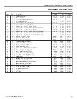
REPLACMENT PARTS LIST

Item

Qty.

Description

Leveler Length

6’ Long

8’ Long

10’ Long

1

1

Frame Weldment

673 xxx

673 xxx

673 xxx

2

1

Platform Weldment

436 xxx

436 xxx

436 xxx

3

1

Lip Weldment

421.xxx

421.xxx

421.xxx

4

1

Lip Out Lug/Lever

142586

142586

142586

5

2

Lip Hinge Pin 6' Wide

562.112

562.112

562.112

2

Lip Hinge Pin 6.5' Wide

562.113

562.113

562.113

2

Lip Hinge Pin 7' Wide

562.111

562.111

562.111

2

Lip Hinge Pin 6' Wide (Stainless Steel)

490.105

490.105

490.105

2

Lip Hinge Pin 6.5' Wide (Stainless Steel)

490.106

490.106

490.106

2

Lip Hinge Pin 7' Wide (Stainless Steel)

490.107

490.107

490.107

6

2

Tension Pin, .25Dia. X 1.75L

123960

123960

123960

7

4

Clevis Pin, Headed, .875 x 3.25L Groove ZP

129307

129307

129307

Clevis Pin, Headed, .875 x 3.25L Gr (Stainless Steel)

129309

129309

129309

8

4

Ring, Ext. Retaining, .875OD

129308

129308

129308

9

1

Bolt, Hex .75-10UNC x 3L ZP

51186

51186

51186

10

1

Nut Hex .75-10UNC ZP

51517

51517

51517

11

1

Bolt Hex .5-13UNC x 1.75L G5 ZP

58016

58016

58016

12

2

Nut Jam .5-13UNC

51505

51505

51505

13

1

Lip Crank

129070

129070

129070

14

3

Torsion Spring 180 Deg. 1.131 OD MWG

120461

120461

120461

15

3

Clevis Pin .5 x 4L HD ZP

117066

117066

117066

16

2

Lip Link

116690

116690

116690

17

1

Clevis Pin, Headed .5 Dia. 1.75L 1Hole ZP

52464

52464

52464

18

7

Cotter Pin .125 Dia. X 1L ZP

51901

51901

51901

19

10

Flat Washer .500 Flat MED ZP

51709

51709

51709

20

8

Flat Washer .375 Flat MED ZP

51700

51700

51700

21

1

Chain 7mm Gr30 LD RTG 1300Lb. ZP

512.105

512.108

512.106

22

2

Chain Shackle, 3/8

51137

51137

51137

23

1

Air Tower Assembly 120V/1Ph 3 Stage

130386

130387

130387

1

Air Tower Assembly 208-230V/1Ph 3 Stage

130388

130389

130389

24

2

Round .312 Dia. X 46.5L

117070

117070

117070

25

2

Bar .25 x 1.25 x 9L Hole

116943

116943

116943

26

1

Hydrachek Bore (1Dia)

51147

51147

51147

27

2

Washer .547ID 2.25OD .25Thk ZP

121580

121580

121580

28

2

Bolt .500-13UNC 3.5L Hex ZP

111359

111359

111359

29

1

Nut .500-13UNC Nylock Jam ZP

112965

112965

112965

30

1

Clevis Pin .5 x 2.25L Hole ZP

52418

52418

52418

31

2

Safety Leg 3 06 x 7L

142583

142583

142583

32

1

Round .5Dia. 28.25L HR M1020 (Non STO Units Only

493.100

493.100

493.100

33

1

S-Hook .219 Wire (Welded Lip With STO Only)

51102

51102

51102

34

1

Chain Assembly Lanyard Twist #1/0 ZP

510.100

510.100

510.100

35

1

Clevis Pin .5 Dia 1.25L Hole ZP (Welded Lip Only)

112686

112686

112686

36

1

Cam MBDC .375 x 4 x 5.88 M1020 (Welded Lip Only)

116655

116655

116655

37

1

Lanyard Assembly Air Tower

121042

121042

121042

38

1

4" Deep Pit Conversion Platform (DPC Only)

665.xxx

665.xxx

665.xxx

Содержание Genisys AL-900

Страница 1: ...AL 900 Dock Leveler Owner s Manual By Rite Hite This Manual Covers Dock Levelers Built After Serial Numbers 07DD400623M and up Publication AMEN00044 2017 01 27 part of the SMOOTH TRANSITION DOK SYSTEMTM ...

Страница 2: ...GENISYS AL 900 Dock Leveler Owner s Manual 2 Publication AMEN00044 2017 01 27 ...

Страница 3: ...ch can be fitted to your specific operation Call your local representative or Rite Hite at 414 355 2600 The Rite Hite products in this manual are covered by one or more of the following U S patents 5882167 6065172 6070283 6085375 6092970 6106212 6116839 6190109 6276016 6311352 6318947 6322310 6360394 6368043 6431819 6488464 6524053 6726432 6773221 6832403 6880301 7032267 7062814 7213285 7216391 73...

Страница 4: ...rate or become unreadable RITE HITE Corporation does not recommend any particular lockout device but recommends the utilization of an OSHA approved device refer to OSHA regulation 1910 147 RITE HITE Corporation also recommends the review and implementation of an entire safety program for the Control of Hazardous Energy Lockout Tagout These regulations are available through OSHA publication 3120 Th...

Страница 5: ...ion if applicable and you have visually inspected to be sure truck trailer is securely held in place by a vehicle restraint or wheel chock per OSHA regulations NEVER operate the leveler with you anyone or anything on or in front of the leveler or without a truck trailer parked in position or from on the truck trailer bed DO NOT operate with anyone under platform or in front of the lip When leveler...

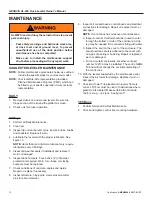
Страница 6: ... main power source as shown under Safety Warnings on the inside front cover of this manual Always barricade the leveler at dock level and drive level to prevent any unauthorized use of the leveler Remove the Maintenance Support For Maintenance Support removal have an assistant raise the leveler to its highest position with lip fully extended Lift the support off base Return the Maintenance Support...

Страница 7: ...representative offers owners the option of a Planned Maintenance Program P M P As part of this service your local Rite Hite representative will do all routine maintenance lubrication and adjustments 6 Dock equipment that is structurally damaged shall be removed from service inspected by a manufacturer s authorized representative and repaired as needed before being placed back in service 7 The manu...

Страница 8: ...ic Return to Dock ARTD If the lip is on the truck trailer and the truck departs the leveler will move to its lowest position and the lip will begin to lower As the lip drops toward the pendant position the ARTD system automatically returns the leveler to the stored position without operator assistance BELOW DOCK LOADING OPERATION 1 Activate the leveler by pushing and holding the RAISE button until...

Страница 9: ...sition 3 When loading unloading is complete continue with normal operation or return the leveler to stored position See Storing Leveler FIGURE 8 END LOAD OPERATION EQUIPPED WITH SAFETY LEGS STORING LEVELER 1 To store the leveler push and hold the RAISE button until leveler is about 6 inches above dock level and lip is fully pendant 2 Release RAISE button Leveler will lower to dock level with lip r...

Страница 10: ...d and replace if worn or damaged 6 Inspect dock bumpers Four inches 4 of bumper protection is required Worn torn loose or missing bumpers must be replaced 7 Check conditions of concrete angles and welds Repair or replace if necessary 8 Inspect structure hinge pins clevis pins and cotter pins for abnormal wear 9 Inspect all conduit boxes control boxes and electrical connections for damage Repair or...

Страница 11: ...N00044 2017 01 27 11 FIGURE 10 LEVELER LUBRICATION OIL SAE 30 Weight Anti Seize FIGURE 11 TUB PLACEMENT Attach chain assembly to d rings on Tub both sides Stops for side Tub opening on Leveler Frame MAINTENANCE CONT Stops for side Tub opening on Leveler Frame ...

Страница 12: ...h has been adjusted correctly and holds the lip out as the platform lowers Test unit three times to make sure it latches all three times if not readjust NOTE DO NOT over adjust the lip latch bolt When properly adjusted the lip should just latch in If you have over adjusted the lip may not release or it will bend the delatch rod over time Re adjust bolt until lip no longer latches and then make one...

Страница 13: ...ill not extend a Debris in lip hinge or lubrication needed b Lip out mechanism or below dock actuator is damaged a Remove dirt debris and corrosion from lip hinge and or lubricate b Repair or replace damaged components 3 Lip remains fully or partially extended a Debris in lip hinge b Lip out mechanism or below dock actuator is damaged c Lip impacted or bent a Remove debris from lip hinge b Repair ...

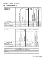
Страница 14: ...S T C U D O R P E T I H E T I R DOK COMMANDER CONTROLS PUSH BUTTONS C D V 2 1 C D V 2 1 C D V 2 1 ARTD INPUT OVERHEAD DOOR OPEN INTERLOCK INPUT OHD ITL LEVELER STORED INTERLOCK TO UNLOCK UNLK ITL RAISE PUSH BUTTON MOTOR CONTACTOR OUTPUT LVLR CONTR 12VDC POWER SUPPLY OK LEVELER SOLENOID 1 LIP OUT K1 STANDARD LEVELER SOLENOID 1 LIP OUT K1 E STOP EQUIPPED AUX BOARD POWER SUPPLY OK TERMINAL BLOCK NO J...

Страница 15: ...A 110 120 1 60 75HP 10 1HP 11 2 208 240 1 50 75HP 5 0 1HP 6 7 208 240 1 60 75HP 5 0 1HP 7 0 208 240 3 60 1 0 HP 3 8 3 6 380 415 3 50 1 0 HP 2 5 2 0 440 480 3 60 1 0 HP 1 9 1 8 575 3 60 1 0 HP 1 5 1 5 110 120 1 60 1 0 HP 21 2 19 0 208 240 1 50 1 0 HP 17 6 16 0 208 240 1 60 1 0 HP 10 6 9 5 208 240 3 60 1 0 HP 5 4 3 6 380 415 3 50 1 0 HP 2 3 2 0 440 480 3 60 1 0 HP 2 5 1 8 575 3 60 1 0 HP 2 4 1 5 DOC...

Страница 16: ...CT SHALL BE LOCATED WITHIN A 50 FT RADIUS AND BE VISIBLE FROM THE CONTROL BOX LOCATION REFERENCE LATEST EDITION OF NEC SECTION 430 G G G BLOWER MOTOR 1300 WATTS MAXIMUM SEE MOTOR FLA CHART 115 1 50 60 Hz INTERMITTENT DUTY 1L2 MOT BLOWER MOTOR 1533 WATTS MAXIMUM SEE MOTOR FLA CHART 208 240 1 50 60 Hz INTERMITTENT DUTY J BOX J BOX MOTOR PIT J BOX MOTOR LEGEND NOTE 1 All Incoming Power From Disconnec...

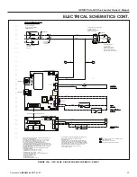
Страница 17: ...SOL3 J2 1 LSOL1 J2 3 LEVELER OPTION BOARD F1 RIBBON CABLE FROM LEVELER POWER CB LSOL3 LSOL2 LSOL1 X2 N X2 N X1 L1 LVLR SOLENOID 20FU1 OVERLOAD PROTECTION PROVIDED BY THERMAL SWITCH REFERENCE LATEST EDITION OF NEC SECTION 430 1L1 BK N WH COM SEE DETAIL B SEE DETAIL C COM SEE DETAIL A COM 1 2 3 1 INSTALL PER LOCAL ELECTRICAL CODES REFER ALL INSTALLATION AND SERVICE TO QUALIFIED PERSONNEL 2 ALL INCOM...

Страница 18: ... RESTRAINT SCHEMATIC GEN II CONTROLS J11 1 J11 2 URC CONTROLS CR1 A CR1 B N O CONTACT MUST BE DRY CONTACT CLOSES WHEN THE RESTRAINT IS ENGAGED OR IN HORN OVERRIDE MODE NOTE DIP SWITCH 2 DOWN IF EQUIPPED UP TO DISABLE GLT ITL J11 1 CMBD PU J11 2 LD3 LD2 GLT ITL CIRCUIT COM COM COM CRx SEE NOTE COM COM CMBD PU CIRCUIT GLT ITL J111 CMBD PU J112 COM DETAIL C RESTRAINT CONTROLS IF EQUIPPED LEVELER POWE...

Страница 19: ...ER POWER CB LSOL3 LSOL2 LSOL1 X2 N X2 N X1 L1 LVLR SOLENOID 20FU1 COM SEE DETAIL B SEE DETAIL C COM SEE DETAIL A COM X2 1 2 3 X2 WH 124 123 X1 RD H1 BN H4 OR 2L1 2L2 2FU1 2FU2 230v H2 VT H3 BL TRANSFORMER PRIMARY FUSING 1 0 AMP 600v CLASS CC REJ DUAL ELM TD X2 WH 120v 60VA TRANSFORMER X1 RD BONDING JUMPER SEE NOTE 6 GND GN X2 WH FROM CUSTOMER MAIN POWER SAFETY PROTECTION DEVICE 208 240v 1PH 60HZ U...

Страница 20: ... CONTROLS J11 1 J11 2 URC CONTROLS CR1 A CR1 B N O CONTACT MUST BE DRY CONTACT CLOSES WHEN THE RESTRAINT IS ENGAGED OR IN HORN OVERRIDE MODE NOTE DIP SWITCH 2 DOWN IF EQUIPPED UP TO DISABLE GLT ITL J11 1 CMBD PU J11 2 LD3 LD2 GLT ITL CIRCUIT COM COM COM CRx SEE NOTE COM COM CMBD PU CIRCUIT GLT ITL J111 CMBD PU J112 COM DETAIL C RESTRAINT CONTROLS IF EQUIPPED LEVELER POWER CB CRx SEE NOTE RAISE COM...

Страница 21: ...GENISYS AL 900 Dock Leveler Owner s Manual Publication AMEN00044 2017 01 27 21 NOTES ...

Страница 22: ...LACEMENT PARTS REPLACEMENT PARTS 54 5 31 31 36 35 38 33 32 39 20 18 18 4 49 15 22 21 22 7 8 5 6 6 9 10 AL9 Parts 53 66 40 62 55 43 44 65 45 46 41 14 42 58 56 20 16 48 15 28 27 19 16 19 17 25 47 18 30 46 13 26 29 27 19 19 14 24 37 23 34 50 42 3 2 51 1 11 12 14 25 63 64 57 52 19 18 47 ...

Страница 23: ...levis Pin 5 x 4L HD ZP 117066 117066 117066 16 2 Lip Link 116690 116690 116690 17 1 Clevis Pin Headed 5 Dia 1 75L 1Hole ZP 52464 52464 52464 18 7 Cotter Pin 125 Dia X 1L ZP 51901 51901 51901 19 10 Flat Washer 500 Flat MED ZP 51709 51709 51709 20 8 Flat Washer 375 Flat MED ZP 51700 51700 51700 21 1 Chain 7mm Gr30 LD RTG 1300Lb ZP 512 105 512 108 512 106 22 2 Chain Shackle 3 8 51137 51137 51137 23 1...

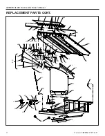
Страница 24: ... 27 REPLACEMENT PARTS CONT 54 5 31 31 36 35 38 33 32 39 20 18 18 4 49 15 22 21 22 7 8 5 6 6 9 10 AL9 Parts 53 66 40 62 55 43 44 65 45 46 41 14 42 58 56 20 16 48 15 28 27 19 16 19 17 25 47 18 30 46 13 26 29 27 19 19 14 24 37 23 34 50 42 3 2 51 1 11 12 14 25 63 64 57 52 19 18 47 ...

Страница 25: ...600 51600 51600 47 4 Nylock Nut 38 16 UNC ZP 51501 51501 51501 48 1 Pin Clevis 5 x 2L Hole HD ZP 52409 52409 52409 49 2 Lip Keeper Weldment Formed 129201 129201 129201 50 1 Cylinder Assembly Stump Out 117130 117130 117130 51 2 Weatherseal Insert PT2 1 513 105 513 104 513 106 2 Weatherseal Insert NB1 1 514 105 514 104 514 106 52 4 Washer Flat 1 125ID 1 75OD 1406Thk ZP 139809 139809 139809 53 1 Wash...

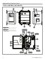
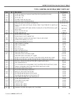
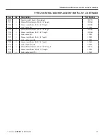
Страница 26: ...ber 1 1 Control Box Complete 228 xxx 2 1 Control Box Enclosure 4 x 4 x 2 N4XF 117342 3 1 Push Button Operator 30 5MM Black NO N12 N4 AB 800T A2D1M 117352 1 Push Button Operator 30 5MM Black NO N4X AB 800H AR2D1M 117315 4 1 Control Box Cover Decal Raise 3 x 3 Hole 30 5MM Oprtr 117414 5 1 Decal V PH FLA 230 xxx 6 1 Decal UL ULC Consult RITE HITE 7 1 Contact Block NO 30 5MM 600V 10A 57077 ...

Страница 27: ...GENISYS AL 900 Dock Leveler Owner s Manual Publication AMEN00044 2017 01 27 27 NOTES ...

Страница 28: ... APPLY IN AVAILABLE SPACE IN ENCLOSURE COVER OR TUB PRODUCTS CORP Milwaukee Wisconsin 53223 800 456 0600 PLATFORM RAISE LIP EXTEND BELOW DOCK ENDLOADING TO STORE LEVELER WARNING OPERATIONAL INSTRUCTIONS RITE HITE PRODUCTS CORP MILWAUKEE WI 53223 1 800 456 0600 WARNING 102 307 301 310 602 309 311 304 302 303 313 701 702 703 4x 4x 4x 208 707 708 2x 2x 213 214 501 718 4x 215 213 214 201 719 720 x4 x4...

Страница 29: ...lug decal 105454 215 1 Fuse cover 5mm x 20mm 144544 216 1 Fuse cover 5mm x 20mm 144544 301 1 Standard Enclosure with decals English 875 103 Standard Enclosure with decals IFC English 875 100 Enclosure with decals other than above Consult Rite Hite for specific part number 875 xxx 1 Enclosure mounting feet includes 4 feet Not needed if ordering new enclosure 147845 302 1 Electrical schematic decal ...

Страница 30: ...NCLOSURE COVER OR TUB PRODUCTS CORP Milwaukee Wisconsin 53223 800 456 0600 PLATFORM RAISE LIP EXTEND BELOW DOCK ENDLOADING TO STORE LEVELER WARNING OPERATIONAL INSTRUCTIONS RITE HITE PRODUCTS CORP MILWAUKEE WI 53223 1 800 456 0600 WARNING 102 307 301 310 602 309 311 304 302 303 313 701 702 703 4x 4x 4x 208 707 708 2x 2x 213 214 501 718 4x 215 213 214 201 719 720 x4 x4 209 709 710 2x 2x 204 202 203...

Страница 31: ...asher 6 51826 704 4 Standoff Male Female 6 32 2 5 length 133365 705 4 Screw round head 6 32 0 25 length 133366 706 4 Lock washer 6 51826 707 2 Screw round head 8 32 0 5 length 51645 708 2 Lock washer star 8 51839 709 2 Screw round head 8 32 0 5 length 51645 710 2 Lock washer star 8 51839 718 4 Standoff Male Female 6 32 0 875 length 115871 719 4 Screw round head 10 32 0 5 length 51629 720 4 Lock wa...

Страница 32: ...tallation instructions If a part is replaced during the standard warranty period it will be covered for the remainder of the warranty period for the dock leveler The above warranties are in lieu of any other warranties either expressed or implied including but not limited to any warranty of merchantability or implied warranty of fitness for a particular application In no event shall Rite Hite or a...

Отзывы: