Installation and opreating instructios for tor-
sionally stiff gear couplings
RDZ…DTO/…DFO
E 06.705
As of: 12.08.2020
Version: 02
Signed: SCCE
Checked: SCHW
No. of pages: 21 Page: 16
Size
RD
Z … DTO
RD
Z … DFO
Angular misalignment
Radial misa-
lignment
[inch]
Axial misa-
lignment
[inch]
Angular misalignment
Axial misa-
lignment
[inch]
Angle per flex.
coupling halve
[°C]
X
[inch]
Angle per flex.
coupling halve
[°C]
X
[inch]
0010
±0.5°
0.012
0.006
±0.005
±0.5°
0.012
±0.002
0015
0.016
0.008
0.016
0020
0.020
0.010
0.020
0025
0.024
0.012
0.024
0030
0.028
0.014
0.028
0035
0.032
0.017
±0.010
0.032
±0.005
0040
0.035
0.020
0.035
0045
0.039
0.021
0.039
0050
0.043
0.026
0.043
0055
0.047
0.029
0.047
0060
0.051
0.032
±0.020
0.051
±0.010
0070
0.059
0.037
0.059
0080
0.067
0.041
0.067
0090
0.075
0.047
0.075
0100
0.083
0.054
±0.030
0.083
±0.015
Table 8.2: Permissible initial offsets
Coupling RDZ
… DFO cannot compensate any radial misalignment.
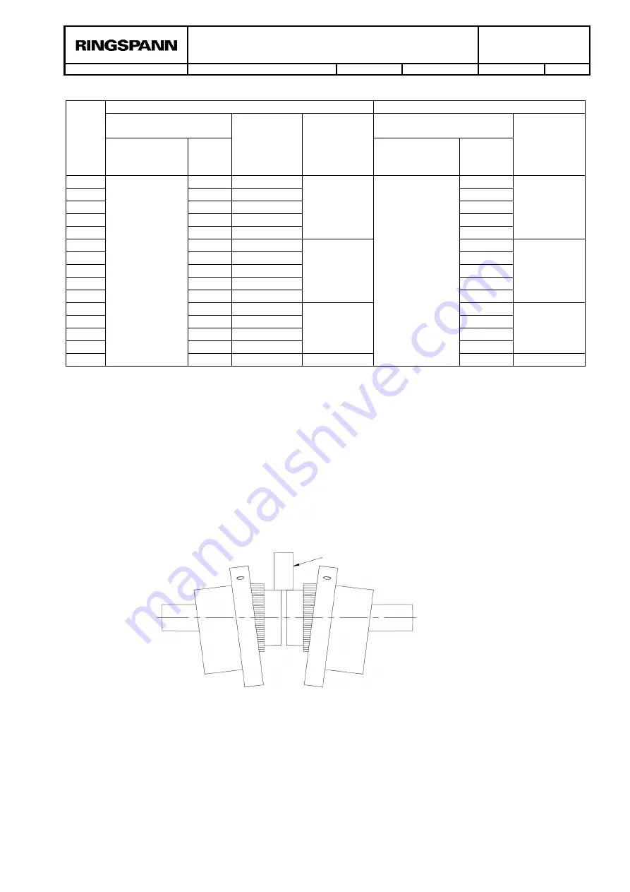
7.3.1 Check the radial misalignment
Measure the radial misalignment by laying a straightedge on both hubs (item 1) and
measuring the gap between the hubs with the help of a feeler gauge (see figure
8.1). The straightedge must hereby be aligned with the axis of the hub. This meas-
urement should be repeated multiple times until the point with the largest gap has
been found. The size of the gap indicates the radial misalignment at that point. The
maximum radial misalignment is given at the point of the largest gap. Alternatively,
a depth gauge or dial gauge can also be used.
Figure 8.1: Measuring the radial misalignment
7.3.2 Check the angular misalignment
Check the angular offset with the help of dial gauges by measuring the axial run-out
at the inner plane surface of the hub (item 1). The dial gauge must hereby be posi-
tioned as close to the outer diameter as possible. The angular offset 'X' in inch
amounts to half of the calculated total value (see figure 8.2). The values of the an-
gular offsets should not exceed the permissible initial offsets specified in table 8.2.
Straightedge


