Installation and opreating instructios for tor-
sionally stiff gear couplings
RDZ…DTO/…DFO
E 06.705
As of: 12.08.2020
Version: 02
Signed: SCCE
Checked: SCHW
No. of pages: 21 Page: 11
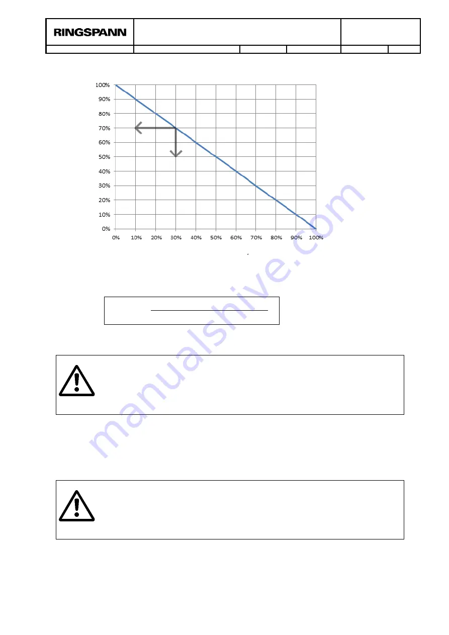
Figure 7.2: Misalignment combination
The misalignment as a percentage is calculated as follows:
7.3. Hub bore specifcations
When boring, or reboring the hub, it must be ensured that:
- the hub is precisely aligned,
- the form and positional tolerances in accordance with DIN ISO 286 are adhered to (see
figure 7.3).
Life-threatening danger!
The max. permissible bore diameters specified in table 7.3 may not be ex-
ceeded. If the permissible values are exceeded, the hub could crack during op-
eration. This could cause life-threatening danger due to flying parts.
Attention!
Never clamp onto the sealing surface! The operator bears the sole responsibil-
ity for any damages that may occur due to defective rework on the unbored /
roughly bored coupling parts.
∆𝐾[%] =
∆𝐾
𝑚𝑎𝑥. 𝑝𝑒𝑟𝑚𝑖𝑠𝑠𝑖𝑏𝑙𝑒 𝑚𝑖𝑠𝑎𝑙𝑖𝑔𝑛𝑚𝑒𝑛𝑡
∗ 100
Radial misalignment
ΔK
r
A
ng
u
la
r
m
is
a
li
gn
m
e
nt
Δ
K
w


