background image

RIGOL 


© 2006 RIGOL Technologies, Inc


User’s Guide for DG2000 Series


2-16 


To Set Noise Signals 

 
Press Noise button, in the Normal Mode, the operation menu will appear at the bottom 
of the screen, see figure 2-22. Set the Pulse parameters by using the operation menu. 
The parameters for Noise waveforms are: Amplitude/ High Level and Offset/ Low Level. 
See figure 2-23. In the operation menu, select    Ampl , and the corresponding 
amplitude will be displayed in inverse color for which users can make a change for the   
the amplitude of Noise. And Noise signal has no frequency or period. 


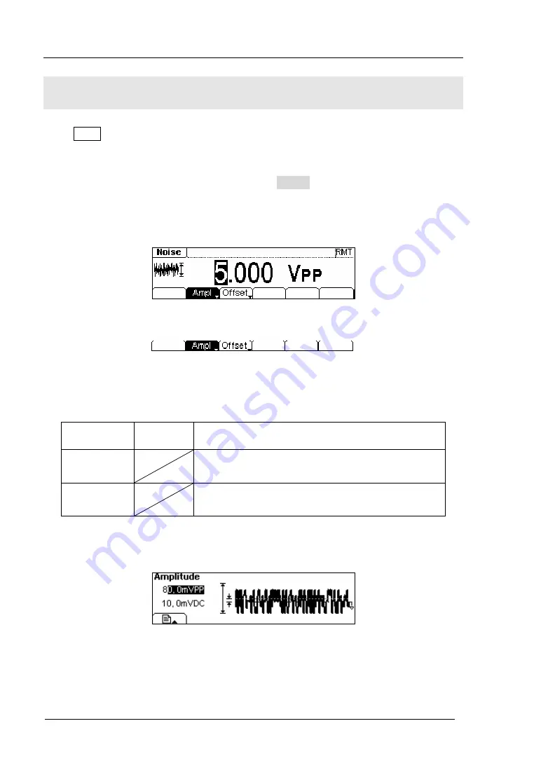
Figure 2-22 The Setting Interface of Noise Signal 


Figure 2-23 The Operation Menu 


Table 2-5 The Menu Explanations of Noise Signal   

 
In the Graph Mode, the waveform is shown in figure 2-24. 


Figure 2-24 The Waveform Parameter in the Graph Mode 

Function  

Menu 

Settings

Explanation


Amplitude/ 

High Level 


Setting the signal Amplitude or High Level; the 
current parameter will switch at a second press. 

Offset/Low 

Level 


Setting the signal Offset or Low Level; the current 
parameter will switch at a second press. 

Содержание DG2000 Series

Страница 1: ...User s Guide RIGOL Publication number UGB02101 1110 Oct 2008 DG2000 Series Function Arbitrary Waveform Generator DG2041A DG2021A 2006 RIGOL Technologies Inc All Rights Reserved...

Страница 2: ......

Страница 3: ...rotected by patent law in and outside of P R China z Information in this publication replaces all previously corresponding material z RIGOL Technologies Inc reserves the right to modify or change part...

Страница 4: ...nd the instrument This generator is grounded through the protective terra conductor of the power cord To avoid electric shock the grounding conductor must be connected to the earth ground Make sure th...

Страница 5: ...6 RIGOL Technologies Inc User s Guide for DG2000 Series III Provide Proper Ventilation Do not operate in wet damp conditions Do not operate in an explosive atmosphere Keep the product s surfaces clean...

Страница 6: ...ices that could result in damage to this product or other property Terms on the product These terms may appear on the product DANGER indicates an injury or hazard that may be immediately happen WARNIN...

Страница 7: ...greatly simplified the operation process Thus users do not have to spend a great deal of time learning and familiarizing the operation of the generator before they can use it proficiently The built in...

Страница 8: ...al output Internal 10 MHz Reference output z Support USB storage device store and read waveform configure parameters or the edited arbitrary waveform with USB devices System Updating could also be per...

Страница 9: ...2 2 To Set Sine Signals 2 3 To Set Square Signals 2 7 To Set Ramp Signals 2 10 To Set Pulse Signals 2 12 To Set Noise Signals 2 16 To Set Arbitrary Signals 2 17 To Generate the Modulated Waveform 2 3...

Страница 10: ...To generate a Linear Sweep 3 16 Example 12 To generate a Burst Waveform 3 18 Chapter 4 Prompt messages troubleshooting 4 1 Prompting Messages 4 1 Troubleshooting 4 17 Chapter 5 Specifications 5 1 Spe...

Страница 11: ...pter 1 Getting Started This chapter covers the following topics General Inspection Handle Adjustment The Front Rear Panel The DG2000 User Interface To Set a Waveform To Set Modulate Sweep Burst To Set...

Страница 12: ...ied with the instrument are listed in chapter 6 Appendix A DG2000 Series Accessories If the contents are incomplete or damaged please contract the local selling representative of RIGOL 3 Inspect the i...

Страница 13: ...DG2000 Function Arbitrary Waveform Generator please grip the handle by the sides and pull it outward Then make the handle rotate to the desired position The operating methods are shown below in figure...

Страница 14: ...ont Rear Panel The Front Panel at a Glance The DG2000 Series Function Arbitrary Waveform Generator has clear and simple front panel See figure 1 3 and figure 1 4 The Front Panel has a knob functional...

Страница 15: ...n the front panel can be only used for the signal output If they are used for input it may make the circuit burned and the instrument in trouble Mode Function Buttons Trigger Control Direction Key LCD...

Страница 16: ...5 The Rear Panel of DG2000 Series Figure 1 6 The Rear Panel Operation Instruction of DG2000 Series 10MHz Reference Input Terminal 10MHz Reference Output Terminal Modulation Input Terminal External Tri...

Страница 17: ...u will appear at the bottom of the screen when you press any menu button These two display modes can be switched to each other by pressing the A button Figure 1 7 The Interface Instruction of Menu Mod...

Страница 18: ...y setting Frequency Period Amplitude High Level Offset Low level the Sine signal with different parameters can be generated Figure 1 10 The Sine Waveform in the Menu Display Mode As shown in figure 1...

Страница 19: ...button and the waveform icon turns into Pulse with a Pulse typeface in the state area DG2000 Series Generator can generate Pulse signal with frequency from 500 Hz to 16MHz and variable Pulse Width an...

Страница 20: ...bitrary waveform signals with at most 512K points and 12MHz frequency By setting Frequency Period Amplitude High Level Offset Low level arbitrary waveform signals with different parameters can be gene...

Страница 21: ...re set by using the menu buttons The modulated waveform can be changed by changing the parameters such as Type Internal External Modulation Depth Frequency Waveform etc DG2000 Series can modulate wave...

Страница 22: ...ed Burst Figure 1 19 The Burst Waveform in the Menu Display Mode Term Explanation Burst Output Waveforms with set cycle times Burst can last for certain times of waveform cycle N Cycle Burst or be con...

Страница 23: ...ously generate burst At this time press Trigger button the instrument will shift from the Automatic Trigger mode into Manual Trigger mode z When the generator uses the External Trigger Mode if the Swe...

Страница 24: ...e keypad The instruction below will help you familiarize with the Digital Input Function 1 Direction Key and the Knob 2 Keyboard Figure 1 21 The Front Panel Digital Input 1 Use the Direction keys to m...

Страница 25: ...ll Utility and Help Button 1 The Store Recall Button is used to store waveform data and configure information 2 The Utility Button is used to set the auxiliary system function change the output config...

Страница 26: ......

Страница 27: ...de A Setting Sine Signal Sine Setting Square Signal Square Setting Ramp Signal Ramp Setting Pulse Signal Pulse Setting Noise Signal Noise Setting Arb Signal Arb Settig Logic Signal Output Digital Outp...

Страница 28: ...the operation menu will pop out Press the corresponding button to set the parameter For example if you want to change the frequency press any menu button and select Freq menu The direction button will...

Страница 29: ...he frequency parameter will show in the parameter area then Users can change the frequency value by using the direction button and the knob or the keypad Figure 2 3 The Setting Interface of Sine Signa...

Страница 30: ...rameter The current operation is displayed in inverse color 2 Input the Desired Frequency Use the keypad to input the parameter value directly and press the corresponding button to select the paramete...

Страница 31: ...the function if the current value is valid for the new waveform it will be used sequentially If you want to set the waveform by high Level or Low Level press Ampl HiLev or Offset Lolev again switch t...

Страница 32: ...the current value is valid for the new waveform it will be used sequentially 2 Input the Desired Offset Use the keypad or the knob to input the desired value choose the unit and press the correspondin...

Страница 33: ...ding parameter will be displayed in inverse color for which users can make a change Figure 2 9 The Setting Interface of Square Signal Figure 2 10 The Operation Menu Table 2 2 The Menu Explanations of...

Страница 34: ...ide for DG2000 Series 2 8 Term Explanation Duty Cycle The percentage that the High Level takes up in the whole Period Please Note for the Frequency Duty Cycle Value Below 8MHz 20 to 80 From 8MHz to 16...

Страница 35: ...ging the function if the current value is valid for the new waveform it will be used sequentially 2 Input the Desired Duty Cycle Use the keypad or the knob to input the desired value choose the unit a...

Страница 36: ...hich users can make a change Figure 2 13 The Setting Interface of Ramp Signal Figure 2 14 The Operation Menu Table 2 3 The Menu Explanations of Ramp Signal Function Menu Settings Explanation Frequency...

Страница 37: ...ging the function if the current value is valid for the new waveform it will be used sequentially 2 Input the Desired Symmetry Use the keypad or the knob to input the desired value choose the unit and...

Страница 38: ...rse color for which users can make a change Figure 2 17 The Setting Interface of Pulse Signal Figure 2 18 The Operation Menu Table 2 4 The Menu Explanations of Pulse Signal Function Menu Settings Expl...

Страница 39: ...itude Negative Pulse Width the time span between thresholds of 50 of the falling edge amplitude to the next 50 of the rising edge amplitude Edge Time The time span between the thresholds of the 10 to...

Страница 40: ...rument is powered or the set value beforehand When changing the function if the current value is valid for the new waveform it will be used sequentially 2 Input the Desired Pulse Width Use the keypad...

Страница 41: ...or the new waveform it will be used sequentially 2 Input the desired Edge Time Use the keypad or the knob to input the desired value choose the unit and press the corresponding button The Generator wi...

Страница 42: ...splayed in inverse color for which users can make a change for the the amplitude of Noise And Noise signal has no frequency or period Figure 2 22 The Setting Interface of Noise Signal Figure 2 23 The...

Страница 43: ...operation menu select Freq and the corresponding frequency will be displayed in inverse color for which users can make a change Figure 2 25 The Setting Interface of Arbitrary Signal Figure 2 26 The O...

Страница 44: ...Volatile Memory the Stored Menu and the Delete Menu will hide z When there is no waveform in the Volatile Memory the Volatile menu will hide Function Menu Settings Explanation Built in Select one of...

Страница 45: ...rms Menu In the Graph Mode the waveform is shown in figure 2 29 Figure 2 29 The Waveform Parameter in the Graph Mode Exponential Rising Waveform Function Menu Settings Explanation ExpRise Select the b...

Страница 46: ...Settings Explanation Local Disk U Disk When U Disk is connected Select display route for the system information State Setting of the Generator Data Arbitrary waveform file Type All All types of docume...

Страница 47: ...Operation Menu Table 2 10 The Menu Explanations of Waveform Removal Function Menu Settings Explanation Local Disk U Disk When U disk is connected Select display route for the system information State...

Страница 48: ...orm Edition Instructions z When there is no waveform stored in the Non Volatile Memory the Stored Menu and the Delete Menu will hide z When there is no waveform in the Volatile Memory the Volatile men...

Страница 49: ...meters Figure 2 34 The Operation Menu Table 2 12 The Explanations of Waveform Parameters Function Menu Settings Explanation Period Setting the Period for the Waveform LevelHi Setting the Level High fo...

Страница 50: ...n be created In the default setting the voltage of point 1 is High Level the time is at 0 s while the voltage of point 2 is Low Level and the time is the half of the set Cycle period To Set the Interp...

Страница 51: ...be edited Time Set time for the Selected point Voltage Set Voltage for the Selected point Insert Insert a new point between the defined points Use the Time and Voltage to define the new point Remove R...

Страница 52: ...ce Figure 2 36 The Operation Menu Table 2 14 The Menu Explanations of Saving New Waveform Function Menu Settings Explanation Local Disk U Disk When a U disk is connected Select display path for the sy...

Страница 53: ...the old one will be erased z For a waveform containing points below 128K the current position will be used z For a waveform containing points from128K to 256K two sequential position will be used z F...

Страница 54: ...e 2 38 The Operation Menu Table 2 15 The Menu Explanations of Editing Stored Waveform Function Menu Settings Explanation Local Disk U Disk When a U disk is connected Select display path for the system...

Страница 55: ...Arb Edit Delete to delete a waveform Select the desired waveform to be deleted which will be displayed in inverse color and press Remove to delete it Instruction The Ultrawave software can be used to...

Страница 56: ...ing Frequency Modulating Waveform and Carrier Waveform in FM users can set the Source Internal External Frequency Deviation Modulating Waveform and Carrier Waveform in FSK users can set the Source Int...

Страница 57: ...m Press Mod Type AM enter the following interface Figure 2 41 The Operation Menu Table 2 16 The Menu Explanations of the AM Parameters Function Menu Settings Explanation Type AM Amplitude Modulation I...

Страница 58: ...Modulation Depth The Amplitude Range also called Percentage Modulation Modulation Depth varies from 0 to 120 z In the 0 Modulation the output amplitude is the half of the set one z In the 100 Modulat...

Страница 59: ...er Waveform and the Modulating Waveform In FM the Frequency of the Carrier Waveform varies with the instantaneous voltage of the modulating waveform The Parameters for the FM are shown in figure 2 43...

Страница 60: ...the Frequency Deviation between the Modulating Waveform and the Carrier Waveform FMFreq Set the modulating waveform frequency Frequency Range 2mHz 20kHz Only Internal Shape Sine Square Triangle UpRam...

Страница 61: ...d the Carrier Frequency should be equal to or less than maximum frequency of the selected function plus 100 kHz z For an External Source the Deviation is controlled by the 5V voltage Level of the Conn...

Страница 62: ...he Signal Voltage Level offered by the Ext Trig FSk Burst connector in the rear panel z If you choose the Internal Modulation the frequency at which the output frequency shifts between the carrier fre...

Страница 63: ...se the rear Ext Trig FSk Burst connector to choose the external source HopFreq Set the Hop Frequency Range 1 Hz 40MHz FSK Rate Set the frequency at which the output frequency shifts between the carrie...

Страница 64: ...Waveform and the Modulating Waveform In PM the Phase of the Carrier Waveform varies with the instantaneous voltage Level of the modulating waveform The Parameters for the PM are as shown in figure 2 4...

Страница 65: ...se Deviation between the Modulating Waveform and the Carrier Waveform ranging from 0o to 360o Freq Set the modulating waveform frequency Frequency Range 2mHz 20kHz Only Internal Shape Sine Square Tria...

Страница 66: ...eform The Parameters for the PWM are shown in figure 2 52 Figure 2 52 The Setting Interface of the PWM Waveform The PWM function is only for modulating the Pulse wave Once in the other wave interface...

Страница 67: ...uty z The max range of WidDev is the minimum in width period width Function Menu Settings Explanation Type PWM Pulse Width Modulation Internal Choose the Internal source SrcInt SrcExt external Use the...

Страница 68: ...cy at the sweep rate you specify Sweeping can be generated by Sine Square Ramp or Arbitrary Waveforms Pulse Noise and DC are not allowed Figure 2 55 The Setting Interface of Sweep Waveform Press Sweep...

Страница 69: ...enter Frequency of the Sweep Stop Span Set the Stop Frequency of the Sweep Set the Frequency Span of the Sweep Time Set the Time Span of the Sweep for which the Frequency changes from the Start Freque...

Страница 70: ...each other z To Sweep upward set the Start Frequency lower than the Stop Frequency or set a positive frequency interval z To Sweep downward set the Start Frequency higher than the Stop Frequency or s...

Страница 71: ...waveform cycle N Cycle Burst or when the external gated signals Gated Burst is applied any waveform could be used But noise can only be used in Gated Burst Press Burst button in the Normal Mode the o...

Страница 72: ...Number of the bursts in a N Cycle Set the Number of the bursts in a N Cycle to be infinite Phase Set the Start Phase of the Burst Period Set the Period of the Burst Delay Set the Delay of the burst So...

Страница 73: ...allowed z For an infinite cycle Burst External or Manual Trigger is needed to activate burst Phase Define the Start and the Stop Point in a waveform The phase varies from 360 to 360 and the default s...

Страница 74: ...enu Table 2 23 The Menu Explanations of Gated Burst Function Menu Settings Explanation Gated Set the Gated Mode Polarity Pos Neg Set the Polarity of the Gated Signal Phase Set the Start Phase of the G...

Страница 75: ...2 64 The Operation Menu Table 2 24 The Menu Explanations of Store and Recall Function Menu Settings Explanation Local Disk U Disk When U Disk is connected Choose display route for the system informat...

Страница 76: ...ed function including the Arbitrary Waveform Frequency Amplitude DC Offset Duty Cycle Symmetry and other modulation parameters used To Save the Instrument State following the steps 1 Choose the file T...

Страница 77: ...ocument will cover the old one To save the data following the steps 1 Set the file Type to store Press Store Recall State data and choose data as the storage type 2 Choose the location of the file The...

Страница 78: ...sion 1 Connect DG2000 with DS1000 to sample data 2 Connect the USB Host Interface of DG2000 with the USB Device Interface of DS1000 View the waveform in DS1000 following the steps below View the Acqui...

Страница 79: ...you imagine This is because that DG2000 considers the acquired 512K points as a period If you want to get the real period of the generated waveform you have to multiple the frequency value shown on DG...

Страница 80: ...Interface of USB Storage 1 Install the Mobile Storage Insert the mobile memory to the USB interface on the front panel and the screen will show 2 Choose the Mobile Memory Press Disk move the cursor up...

Страница 81: ...tion button to select the desired character When the character is in inverse color press Select to input it Figure 2 71 The File Storage Interface Figure 2 72 The Operation Menu Table 2 25 The Menu Ex...

Страница 82: ...the English Interface 2 Input the file name NewFile Use the Knob to adjust the cursor to the right character and press Select Repeat this until you have selected all the characters needed Press to ch...

Страница 83: ...you need with the help of the page controller and the 1 9 button on the keypad 4 Edit the wrongly input When a file name is wrong move the cursor to the character and press Remove to delete it and ree...

Страница 84: ...nal or not The Output setting provides the parameter setting for Load Impedance Range Normal Inverse and Phase The Interface Setting offers the storage and load of the configure parameter setting for...

Страница 85: ...onnector on the front panel Sync On Off Off Deactivate the Sync Signal of the Sync Connector on the front panel Output Set the Output parameter Table 2 27 I O Set the I O Table 2 28 System Set the Sys...

Страница 86: ...tage Level To Shift into the Arbitrary Waveform Output 1 Press Utility DC On Off DC Off close the DC output and return the output of the Arbitrary Waveform 2 Press any functional button and the wavefo...

Страница 87: ...y Waveform the Sync Signal is a Square Waveform with 50 Duty Cycle At the time when the first output waveform point is generated the Sync Signal Voltage is TTL High Level z For AM FM and PM in Interna...

Страница 88: ...0 Series 2 62 z For the External Gated Burst the Sync Signal follows the External Gated Signal But please note that this signal will not turn Level Low until the last period end If the Waveform has a...

Страница 89: ...2 27 The Menu Explanations of Output Setting Function Menu Settings Explanation Load High Z Set the Load connected to the Output Connector Set the Load connected to the Output Connector as High Z Ran...

Страница 90: ...enter the following interface Please note that the Load Parameter shown on the right bottom is the default when the power is on or the pre set load value If the current value is valid for the output...

Страница 91: ...form output No offset voltage will change while the waveform is inversed An inversed waveform will be displayed in the Graph Mode Figure 2 80 The Normal Waveform Figure 2 81 The Inverse Waveform 3 To...

Страница 92: ...gs Explanation LAN Set the LAN configuration parameter GPIB Set the GPIB Address USB See USB equipment address RS232 Set the RS232 Interface Set the GPIB address as any value within 0 30 The default s...

Страница 93: ...Utility I O LAN enter the following interface Figure 2 84 The Operation Menu Table 2 29 The Menu Explanations of LAN Setting IP Setup Press Utility I O LAN IPSetup enter the following interface Figure...

Страница 94: ...Off Off Close the DHCP setting set the IP address manually IP addr Set the IP address IP Mask Set the IP Mask Gate Way Set the Gate Way Instruction Open the DHCP Press DHCPon allot the IP address dyna...

Страница 95: ...he Host name will be stored in the Non Volatile Memory Domain Name Set the Domain Name with letter number dash and dot Consult with your network administrator for the Domain name you need Use the knob...

Страница 96: ...es Inc User s Guide for DG2000 Series 2 70 The range of the GPIB interface address is 0 30 and the default value is 7 Press Utility I O GPIB enter the interface below Figure 2 88 The Interface of Sett...

Страница 97: ...s of Setting RS232 Function Menu Settings Explanation Baud Set the RS232 Baud Rate Parity Set the RS232 Parity and the data digit Baud Rate Set the RS232 Baud Rate Make sure that the Baud Rate matches...

Страница 98: ...On Off Off Close Beeper On Activate the Screen Guard function Screen Guard will be on if no action is taken within 3 minutes Press any button to return the display screen Svr on off Off deactivate the...

Страница 99: ...choices are available the default setting and the latest Once selected the setting will be used when the instrument restarts Beep Activate or deactivate the sound when an error occurs from the front...

Страница 100: ...guage Press Utility System Lang change the current language Figure 2 91 The Interface of Language Setting 2 Display Control Press Utility System Display enter the following interface Figure 2 92 The I...

Страница 101: ...Settings Explanation Using dot as decimal Decimal Using comma as decimal No Close the Separate Space Use Space as separator Separat On Enable the Separator function According to the different choice...

Страница 102: ...s Figure 2 96 Set the data format 4 Set as decimal press Separat No the example is given as follows Figure 2 97 Set the data foramt 5 Set as decimal press Separat Space the example is given as follows...

Страница 103: ...The Factoruy Default Modulation Default Carrier 1kHz Sine Wave Modulating 100Hz Sine Wave AM Depth 100 FM Deviation 100Hz FSK Hop Frequency 10Hz FSK Frequency 100Hz Sweep Default Start Stop Frequency...

Страница 104: ...down Recall Disabled Display On Error Array Clear Error Storage State and any No change Trigger Default Source Internal Remote I O Configuration Default GPIB Address 7 I O GPIB IEEE 488 Baud Rate 9600...

Страница 105: ...mally To perform a general test needs15 seconds If all the tests have been passed you can use the generator freely If the general test has been passed the screen will show Self Test Passed if not it w...

Страница 106: ...tory When you turn on a new instrument the default number of the calibration is 0 You can get the information of the latest version on the company s website http www rigol com 2 Password This function...

Страница 107: ...you can get help about the operation of the front panel buttons with the Help List Press Help enter the following interface Figure 2 103 The Help Interface Figure 2 104 The Operation Menu Table 2 38...

Страница 108: ...ed using PWM Noise and DC can not be modulated 2 Configure the modulating waveform by pressing the Mod key 3 To change the Carrier parameter press the lighted function key Sine Square etc 4 To turn of...

Страница 109: ...instrument as its default state 8 Synchronize multiple instruments By using the external I O of the generator connect the instrument to the other kinds of instruments to perform the synchronous contr...

Страница 110: ......

Страница 111: ...Freq Period and choose Freq which will display in reverse color 2 Enter 20 from the keypad and choose the unit kHz The Frequency is set as 20 kHz 2 Set the Amplitude 1 Press Ampl HiLev to choose Ampl...

Страница 112: ...e Amplitude 1 Press Ampl HiLev and choose Ampl which will display in reverse color 2 Enter 2 from the keypad and choose the unit Vpp to set the Amplitude as 2 Vpp 3 Set the Offset 1 Press Offset LoLev...

Страница 113: ...mplitude 1 Press Ampl HiLev and choose Ampl which will display in reverse color 2 Enter 100 from the keypad and choose the unit mVpp to set the Amplitude as 100mVpp 3 Set the Offset 1 Press Offset LoL...

Страница 114: ...mpl HiLev and choose HiLev which will display in reverse color 2 Enter 50 from the keypad and choose the unit mVpp to set the High Level as 50mVpp 3 Set the Low Level 1 Press Offset LoLev to choose Lo...

Страница 115: ...RIGOL Technologies Inc User s Guide for DG2000 Series 3 5 When the Frequency High Level Low Level Pulse Width and Edge Time were set the generated waveform is shown in figure 3 4 Figure 3 4 The Pulse...

Страница 116: ...t load as 50 2 Set the Amplitude 1 Press Ampl HiLev and choose Ampl which will display in reverse color 2 Enter 30 from the keypad and choose the unit mVpp to set the Amplitude as 30mVpp 3 Set the Off...

Страница 117: ...nput 8 from the keypad and choose the unit MHz to set the Frequency as 8MHz 3 Set the Amplitude 1 Press Ampl HiLev and choose Ampl which will display in reverse color 2 Enter 5 from the keypad and cho...

Страница 118: ...g the time and voltage of the points 2 Set the period 1 Press Period which will display in reverse color 2 Input 12 from the keypad and choose the unit s to set the Period as 12 s 3 Set the Voltage Li...

Страница 119: ...efined below in table 3 1 Table 3 1 The Setting of Time and Voltage of the points Point Time Voltage 1 0s 0V 2 4 s 4V 3 8 s 0V 4 10 s 2V 7 Save the Waveform Press Save to store the waveform in one of...

Страница 120: ...Ampl HiLev and choose Ampl which will display in reverse color Enter 2 from the keypad and choose the unit Vpp to set the Amplitude as 2 Vpp 3 Press Offset LoLev and choose Offset which will display i...

Страница 121: ...for DG2000 Series 3 11 At this time the instrument generates the specified AM waveform The Waveform is shown in figure 3 9 Figure 3 9 The AM Waveform 7 Turn off the Modulation Function Press the light...

Страница 122: ...uency as 10 kHz 2 Press Ampl HiLev and choose Ampl which will display in reverse color Enter 2 from the keypad and choose the unit Vpp to set the Amplitude as 2Vpp 3 Press Offset LoLev and choose Offs...

Страница 123: ...RIGOL 2006 RIGOL Technologies Inc User s Guide for DG2000 Series 3 13 Figure 3 10 The FSK Waveform 6 Turn off the Modulation Function Press the lighted Mod Key to turn off the Modulation Function...

Страница 124: ...e Ampl which will display in reverse color then use the keyboard enter 5 and choose the unit Vpp to set the amplitude as 5 Vpp 3 Press Offset Lolev to choose Offset which will display in reverse color...

Страница 125: ...ide for DG2000 Series 3 15 Now the signal generator will export the PWM wave according to your setting the figure is shown below Figure 3 11 The PWM Waveforrn 7 Close the modulation function Press Mod...

Страница 126: ...in reverse color Enter 2 from the keypad and choose the unit Vpp to set the Amplitude as 2 Vpp 3 Press Offset LoLev and choose Offset which will be displayed in reverse color Enter 0 from the keypad a...

Страница 127: ...Figure 3 12 The Sweep Waveform Instructions If necessary you can set the frequency Limits by setting the Center Frequency and the Frequency Range These parameters are similar to the Start and Stop fre...

Страница 128: ...s Ampl HiLev and choose Ampl which will display in reverse color Enter 5 from the keypad and choose the unit Vpp to set the Amplitude as 5 Vpp 3 Press Offset LoLev and choose Offset which will display...

Страница 129: ...Set the Delay Press Delay use the keypad to enter 200 choose the unit s setting the Burst Delay as 200 s At this time the instrument generates the specified 3 Cycle Burst waveform with a period of 10...

Страница 130: ......

Страница 131: ...eform parameter is being altered if the user cancels the operation the message will prompt Selected arb is Inform the user that the selected arbitrary waveform type is the built in ExpRise ExpFall Neg...

Страница 132: ...trument now is UNSECURED Inform the user that the password is correct and the user can calibrate the instrument now The instrument is unsecured Instrument triggered The manual trigger mode is activate...

Страница 133: ...will be covered Press Yes to continue Press Cancel to reselect the place Can t Write this File to system This message appears when the operation of burning menu or programs into the system from the U...

Страница 134: ...4 4 correct this message will appear Wave file will cover If the arbitrary waveform to be stored is larger than 128K other places will be used to store the waveform Mobile disk installation is error...

Страница 135: ...hen a parameter is input inform the user Choose the parameter unit to finish changing the parameter or press Cancel button to cancel the current operation Trigger ignored OUTPUT is off If groups of GE...

Страница 136: ...time between the time trigger is received and the start of the burst Sorry unable to N cycle burst with noise Noise can not be used in the trigger burst mode it can only be used in the gated burst Tri...

Страница 137: ...fied one automatically Sorry unable to modulate Noise Noise Pulse and DC can not be modulated using AM FM PM or FSK methods Sorry unable to modulate DC Noise Pulse and DC can not be modulated using AM...

Страница 138: ...the pulse according to the order below Edge time Pulse Width Period In this case the generator will reduce the Edge Time to cater to the need of the period Amplitude Vrms upper limit 3 536Vrms For exa...

Страница 139: ...he generator will adjust the following parameters automatically in the order below to generate the pulse waveform Edge time Pulse Width Period When the period changes the Edge Time and Pulse Width wil...

Страница 140: ...limit 1 Hz The Ramp wave frequency lower limit is 1 Hz If the specified frequency is lower than 1 Hz the system will adjust the frequency to 1 Hz automatically Pulse Wave frequency upper limit 16MHz T...

Страница 141: ...d lower limit is 62 5ns If the specified period is less than 62 5ns the system will adjust the period to 62 5ns automatically Arb Wave period upper limit 1Ms The Arb Wave Period upper limit is 1Ms If...

Страница 142: ...ed Edge Time should be in the specified period The generator will adjust the Edge Time to meet the need of the period Edge Time 0 625 Pulse Width Pulse width lower limit 12ns In the Pulse mode the Pul...

Страница 143: ...ally Deviation plus Carrier cannot exceed maximum The sum of the Carrier frequency and the deviation frequency should be lower than or equal to the selected maximum frequency plus 100kHz AM Depth uppe...

Страница 144: ...ally PM Frequency lower limit 2mHz The PM Frequency lower limit is 2mHz If the specified PM Frequency is lower than 2mHz the system will adjust the PM Frequency to 2mHz automatically Start Frequency u...

Страница 145: ...ll adjust the Sweep Time to 1 0ms automatically Phase upper limit 360 0 The Phase upper limit is 360 0o If the specified Phase is greater than 360 0o the system will adjust the Phase to 360 0 o automa...

Страница 146: ...utomatically Load Impedance lower limit 1 The Load Impedance lower limit is 1 If the specified Load Impedance is less than 1 the system will adjust the Load Impedance to 1 automatically Start Phase up...

Страница 147: ...lly on 3 Restart the instrument after taking the above steps 4 If it does not work correctly contact RIGOL for our service 2 If the settings are correct but no waveform is generated please follow the...

Страница 148: ......

Страница 149: ...nless specified statement To meet these specifications two conditions must be satisfied first The instrument must be operated continuously for more than 30 minutes within the specified operating tempe...

Страница 150: ...C Temperature index 2 ppm C Frequency Characteristic DG2021A Waveforms Sine Square Ramp Triangle Pulse Noise DC Arb Sine 1 Hz to 25 MHz Square 1 Hz to 25 MHz Pulse 500 Hz to 10MHz Ramp 1 Hz to 250kHz...

Страница 151: ...1 of period 5ns Jitter 1ns 100ppm of period Ramp Wave Characteristics Linearity 0 1 of peak output typical 1kHz 1Vpp symmetry 100 Symmetry 0 to 100 Pulse Wave Characteristics Pulse Width 2000s max per...

Страница 152: ...tput Impedance 50 typical Isolation 42 Vpk max to Earth Protection Short circuit protected Overload disables the waveform output automatically AM Modulation Carrier Waveforms Sine Square Ramp Arb Sour...

Страница 153: ...1 Source Internal External Manual Burst Waveforms Sine Square Ramp Pulse Noise Arb Types Count 1 to 1 000 000 periods infinite gated Start Phase 360 to 360 Internal Period 1 s 500 s 1 Gate Source Exte...

Страница 154: ...00 ns typical Trigger Output Level TTL compatible into 1k Pulse Width 400ns typical Output Impedance 50 typical Maximum Rate 1 MHz Notes 1 z The amplitude range 50 The output frequency 10MHz the ampli...

Страница 155: ...MS 45 440Hz CAT II Consumption Less than 50W Fuse 2A T Level 250V Environment Operation 10 40 Temperature Range Non operation 20 60 Cooling Natural cooling Below 35 90 relative humidity Humidity Range...

Страница 156: ......

Страница 157: ...DG2000 Series Accessories Standard Accessories z A Power Cord that fits the standard of the destination country z A USB Data Cable z A Use s Guide Optional Accessories z BNC cable z RS 232 data cable...

Страница 158: ...efective To get repair service or obtain a copy of the whole warranty statement please contact with your nearest RIGOL sales and service office RIGOL do not provide any other warranty items except the...

Страница 159: ...nts Cleaning Check the instrument frequently according to the operation conditions follow the steps below to clean the exterior surface of the instrument 1 Wipe the dust on the outside of the instrume...

Страница 160: ...estic Please call Tel 86 10 8070 6688 Fax 86 10 8070 5070 Service Support Hotline 800 810 0002 9 00 am 5 00 pm from Monday to Friday Or by e mail Service rigol com Or mail to RIGOL Technologies Inc 15...

Страница 161: ...Store Recall 2 50 2 51 2 60 Test 2 79 The DG2000 User Interface 1 7 The Front Rear Panel 1 4 The interconnection of DG2000 and DS1000 2 52 The Menu Graph Mode 2 2 To Generate Burst 2 45 To Generate S...

Отзывы: