


5
MOUNTING TO A VALVE
RIFT
® 200 Electric Actuators have mounting options that conform to ISO:5211 which enables them, where
applicable, to be direct mounted to similarly compliant valves, thus eliminating the cost and additional height
of a traditional box section (or similar)
‘
mounting kit
’.
ISO:5211 introduced a system to ensure the actuator
drive is concentric and in vertical alignment with the stem or shaft of the valve to be driven, and the actuator
is solidly mounted to the valve. All aspects of valve and actuator mounting are critical to the correct
performance of the assembled valve and actuator.
The
RIFT
® 200 has a base flange, giving an ISO:5211 mounting option as follows;
The female metric threads in the base flanges are zinc plated steel; these are specialist fixings designed for
use in plastic injected molded components and are inserted into the flange during the injection molding
process.
The flanges are changed by removing the 4 x M4 socket countersunk screws, removing the existing flange
and drive adapter, inserting the other flange and correct drive adapter in the correct orientation and
replacing the 4 socket countersunk screws. If required, an appropriate bolt can be fitted to one of the fixings
and used to assist in levering the mounting flange from the base.
Ensure that the height of the stem or shaft to be driven, from the valve
’
s ISO:5211 platform to the
top of the stem or shaft, does not exceed the maximum depth of the female drive output to be used
as this will push the actuator
’
s internal components upwards which will cause irreparable damage.
Care must be taken when selecting the bolts to secure the valve to the actuator flange to ensure that
the bolts do not reach the solid bottom of the threaded insert before the bolt is tight against the valve
flange.
Ensure that the valve is in the same position as the actuator when assembling the valve to the actuator;
otherwise the opposite position in the valve to the signal sent to the actuator will result. To assist with
this, the closed symbol is molded into the actuator lid to ensure that the closed position/orientation is
known, and the local visual indicator LEDs will indicate the current position of the actuator.
Where the valve is supplied with a lock washer on the stem nut (the nut that compresses either the
Belville washers, or the stem packing), ensure
t
his lock washer is still fitted when
assembling the valve to the actuator, and use washers if necessary to ensure that the lock washer
cannot slide up when assembled and thus become ineffective. This lock washer prevents the stem nut
slackening off during operation.
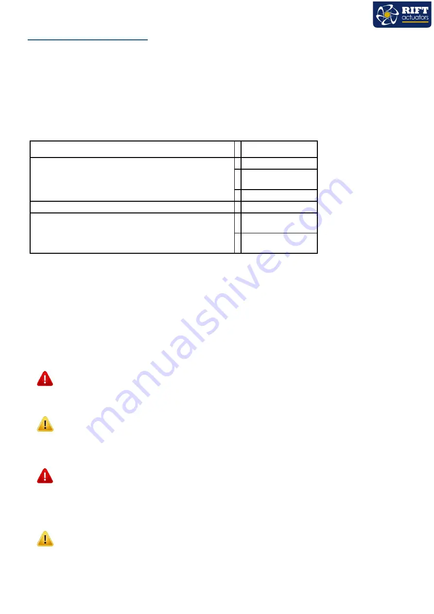
ISO:5211
Large Flange: F07, F10
Dimensions
‘
F
’ |
PCD | No of holes | Metric female thread size? Max
thread depth
F07: 70 | 4 | M8 | 12
F10: 102 | 4 | M10 |
14
Female square drive (mm)
Standard | Option
17 | 22
Maximum depth of female drive output
17mm drive, max
19mm deep
22mmdrive,max
24mm deep
?


