46
APPENDIX
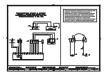
Electrical connections
NOTES
The electrical wirings must be carried out in conformity
with the regulations in force in the countries of destina-
tion, and by qualified personnel.
Riello S.p.A. cannot accept any responsibility for modi-
fications or connections other than those shown in
these diagrams.
Use flexible cables, in accordance with the regulation EN
60 335-1.
All the cables to be connected to the burner must pass
through cable grommets.
The use of cable grommets can take various forms; the
following way is just one possible solution:
RS 50/M
1- Pg 11
Three-phase power supply
2- Pg 11
Single-phase power supply
3- Pg 9
Remote control device TL
4- Pg 9
Remote control device TR or probe (RWF40)
5- Pg 11
Gas valves
(when RG1/CT or LDU 11 leak detection control device
is not fitted)
6- Pg 11
Gas pressure switch or gas valve leak detection con-
trol device
D867
ADJUSTMENT OF THERMAL CUTOUT
Used to avoid the burning of the motor owing to a strong increase
in the absorption, caused by the lack of a phase.
• If the motor is star-driven,
400V
, the cursor must be positioned
on “MIN”.
• If it is delta-driven,
230V
, the cursor is positioned on “MAX”.
If the scale of the thermal cutout does not include the absorption of
rating of the motor at 400V, the protection is guaranteed anyway.
• The model RS 50/M leaves the factory with an electrical supply setting of
400V
. If
230V
power supply is used, change the motor connection
from star to delta and change the setting of the thermal cutout as well.
• The burners RS 50/M have been approved for intermittent operation. This means they should be compulsorily stopped at least once every
24 hours to enable the control box to perform a check of its own efficiency at start-up. Normally, the stopping of the burner is guaranteed by
the boiler's thermostat/pressure switch. If this is not the case, a time switch should be fitted in series to IN to provide for burner shut-down at
least once every 24 hours.
• The burners RS 50/M leave the factory set for two-phase operation, so the thermostat/pressure switch TR must be connected. If you want
the burner to work with single-phase operation, insert (in place of the thermostat/pressure switch TR) a bridge between the terminals T6 - T8
of the plug X4.
MODULATING OPERATION
If the output power regulator kit RWF40 or the converter 0...10V / 4...20mA is connected, in 3-point signal, the thermostat/pressure.
In addition, the function Q13 - Q14 of the regulator RWF40 can substitute the thermostat/pressure switch TL.
In this case, the thermostat/pressure switch TL connected to the X7 must be bypassed.
On the contrary, if you want to maintain the thermostat/pressure switch TL, it must be adjusted so as not to interfere with the working of the
regulator RWF40.
ATTENTION:
- Do not invert the neutral with the phase in the electrical supply line. An inversion would lead to lockout due to ignition
failure.
- Replace the components only with original spare parts.
NOTES
!
D8601
Содержание RS 50/M
Страница 50: ...50...
Страница 52: ...52 0 0 0 1 0 0 0 0 0 0 0 0 0 0 0 1 0 222 3 3 4 5 6 7 2...
Страница 55: ......


