20044359
12
Technical description of the burner
3.10 Control box for the air/fuel ratio (LMV37.4...)
Warning notes
All activities (mounting, installation and service work, etc.)
must be performed by qualified staff.
Before making any wiring changes in the connection area,
completely isolate the plant from mains supply (all-polar dis-
connection). Ensure that the plant cannot be inadvertently
switched on again and that it is indeed dead. If not observed,
there is a risk of electric shock hazard.
Ensure protection against electric shock hazard by providing
adequate protection for the burner control’s connection termi-
nals.
Each time work has been carried out (mounting, installation,
service work, etc.), check to ensure that wiring and parame-
ters is in an orderly state.
Fall or shock can adversely affect the safety functions. Such
units must not be put into operation, even if they do not exhibit
any damage.
Introduction
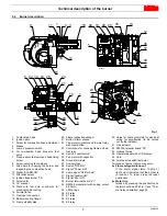
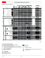
The control box for the air/fuel ratio (Fig. 7), (hereafter referred to
simply as the control box), that equips the burners, carries out a se-
ries of integrated functions in order to optimise burner functioning,
both for single operation and together with other units (e.g. double
furnace boiler or more than one generator at the same time).
The basic functions carried out by the control box relate to:
flame control;
the dosage of air and fuel via the positioning (with direct servo-
control) of the relative valves, excluding the possible play in
the mechanical cam calibration systems;
the modulation of burner output, on the basis of the load
requested by the system, maintaining the pressure or tem-
perature of the boiler at the working values set;
the safety diagnostic of the air and fuel circuits, via which it is
possible to easily identify any causes of malfunctioning.
Mechanical design
The following system components are integrated in the LMV37.4...
basic unit:
•
Burner control with gas valve proving system
•
Electronic air / fuel ratio control
•
Control frequency converter air fan
•
Modbus interface
Installation notes
•
Always run high-voltage ignition cables separately while ob-
serving the greatest possible distance to the unit and to other
cables.
•
Do not mix up live and neutral conductors (fire hazard, danger-
ous failures, loss of protection against electric shock hazard,
etc.).
•
Do not lay the connecting cable from the LMV37.4... to the
AZL2… together with other cables.
Electrical connection of the flame detectors
It is important to achieve practically disturbance- and loss-free sig-
nal transmission:
•
Never run the detector cable together with other cables.
– Line capacitance reduces the magnitude of the flame signal.
– Use a separate cable.
•
Observe the maximum permissible detector cable lengths.
•
The ionization probe is not protected against electric shock
hazard. It is mainspowered and must be protected against ac-
cidental contact.
•
Locate the ignition electrode and the ionization probe such that
the ignition spark cannot arc over to the ionization probe (risk
of electrical overloads).
WARNING
To avoid injury to persons, damage to property
or the environment, the following warning notes
must be observed!
The LMV37.4... is a safety device!
Do not open, interfere with or modify the unit.
The manufacturer will not assume responsibili-
ty for any damage resulting from unauthorized
interference!
WARNING
The first start-up, like every further operation for
the internal settings of the control box, requires
access by means of a password and is only to
be carried out by personnel of the Technical As-
sistance Service who have been specifically
trained in the internal programming of the tool.
Fig. 7
D9300
Содержание RS 28/E
Страница 2: ...Original instructions...
Страница 31: ...Appendix Spare parts 29 20044359 A Appendix Spare parts...


