


20044359
24
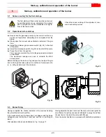
Start-up, calibration and operation of the burner
5.4
Burner calibration
The optimum calibration of the burner requires an analysis of the
flue gases at the boiler outlet.
Adjust successively:
Firing output
Maximum burner output
Minimum burner output
Intermediate outputs between low and high fire
Air pressure switch
Minimum gas pressure switch
5.5
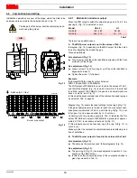
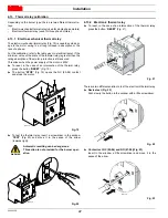
Burner start-up
Feed electricity to the burner via the disconnecting switch on the
boiler panel.
Close the thermostats/pressure switches, set the parameters on
the RWF 55 regulator.
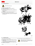
Please refer to the spacific manual for this operation. Turn the
switch of Fig. 27 to position
“ON”
and turn the switch of Fig. 27 to
position
“LOCAL”
.
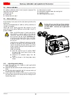
5.5.1
Adjusting gas/air delivery
Adjust the burner up to the maximum output (gas butterfly
valve completely open);
adjust the required maximum output with the gas pressure sta-
bilizer;
set the combustion parameters with the air servomotor and
store the maximum combustion value;
proceed slowly to the decrease of the output by synchronizing
the combustion with the two servomotors and storing the dif-
ferent setting values.
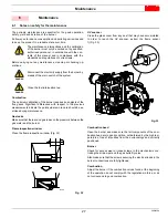
DANGER
Make sure that the lamps or testers connected to
the solenoids, or indicator lights on the solenoids
themselves, show that no voltage is present. If volt-
age is present, stop the burner
immediately
and
check the electrical wiring. When the burner starts,
check the direction of the motor rotation, as indicat-
ed in Fig. 27.
As the burner is not fitted with a device to check the
sequence of the phases, the motor rotation may be
incorrect. As soon as the burner starts up, go in front
of the cooling fan of the fan motor and check it is ro-
tating anticlockwise.
If this is not the case:
place the switch of Fig. 27 in position “
OFF
”
and wait for the control box to carry out the
switch-off phase;
disconnect the electrical supply from the
burner;
invert the phases on the three-phase power
supply.
WARNING
For the start-up procedure and the parameters
calibration, refer to the specific instruction man-
ual of the LMV37... electronic cam supplied with
the burner.
REMOTE
LOCAL
ON
OFF
Fig. 27
D12196
Содержание RS 28/E
Страница 2: ...Original instructions...
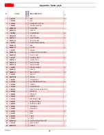
Страница 31: ...Appendix Spare parts 29 20044359 A Appendix Spare parts...


