


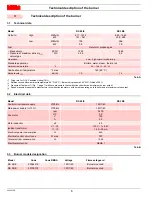


Technical description of the burner
7
20044359
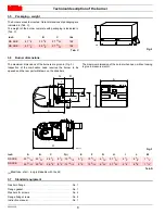
3.4
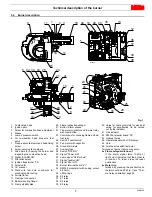
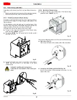
Burner description
1
Combustion head
2
Ignition pilot
3
Screw for combustion head adjustment
4
Sleeve
5
Low air pressure switch
6
Air combustion head pressure test
point
7
Gas pressure test point and head fixing
screw
8
Screw securing fan to sleeve
9
Slide bars for opening the burner and
inspecting the combustion head
10 Signal “ALARM ON”
11 Pilot attachment
12 Ignition transformer “TA”
13 Air actuator
14 UV scanner
15 Plate with four hole knock-outs for
electrical cable routing
16 Air inlet to fan
17 Gas input connection
18 Boiler mounting flange
19 Flame stability disk
20 Flame inspection window
21 Button “Alarm silence”
22 Fan motor contactor and thermal relay
with reset button
23 Control box for checking flame and air/
fuel ratio
24 Switch “Local/remote”
25 Fan motor with capacitor
26 Ground terminals
27 Auxiliary fuse
28 Switch “OFF/ON”
29 Signal “Power ON”
30 Lamp signal “Call for heat”
31 Signal “Ignition ON”
32 Signal “Fuel ON”
33 Burner terminal board “X1”
34 RWF55 modulator (with analog output
4-20 mA)
35 Lifting rings
36 K2 relay
37 K1 relay
38 K3 relay
39 K5 relay
40 Holes for cable grommets for electrical
wiring for accessories (to be carried
out by the installer)
41 Gas actuator
42 RWF55 terminal board “X3”
43 Optional holes
44 Operator panel with LCD display
45 Horn
46 Air pressure switch test point
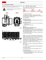
Two types of burner failure may occur:
Flame safeguard lock-out
If the alarm signal lamp 10)(Fig. 1)
lights up, it indicates that the burner is
in lock-out. To reset, press the reset
pushbutton.
Motor trip
release by pressing the pushbutton on
thermal overload, 22)(Fig. 1) see “Ther-
mal relay calibration” page 22.
8
24
21
18
31
32
10
30
29
41
6
28
34 43
42
43
2
1
9
11
3
17
15
16
7
4
19
25
26
23
27
22
33
45
40
20
12
5
35
14
13
44
36
37
39
38
46
Fig. 1
D12063
Содержание RS 28/E
Страница 2: ...Original instructions...
Страница 31: ...Appendix Spare parts 29 20044359 A Appendix Spare parts...


