background image

13

Bolero User Manual A20

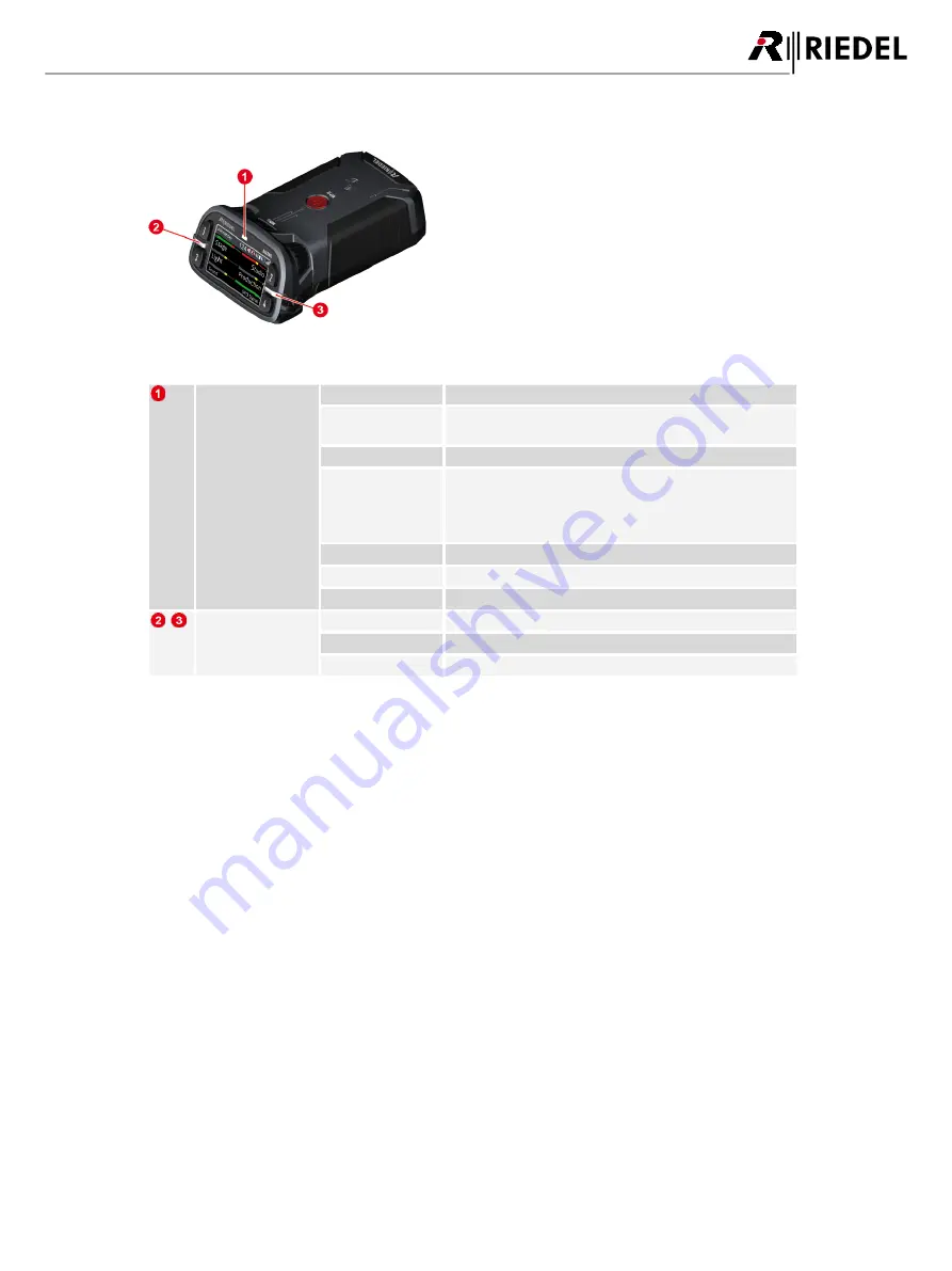
2.2 Status LEDs

Figure 5: Beltpack – Status LEDs (top)

Status

off

Beltpack is turned off

green

·

Beltpack ready (System ok)

·

USB charging, battery full

green blinking

USB charging, battery level 90–99%

red

·

booting

·

Beltpack not registered/not connected

·

low battery level

·

outside the Antenna coverage area

red blinking

critical battery level (<30 minutes of operation)

red fast blinking

critical error (no function)

orange blinking

USB charging, battery level 0–89%

Call

off

no active call

green

incoming call

orange blinking

incoming notification/beep call

Содержание Bolero

Страница 1: ...User Manual A20 03 000HB01EG Bolero Next Generation Wireless ...

Страница 2: ...xposure Information for the Antenna This equipment complies with FCC radiation exposure limits set forth for an uncontrolled environment This equipment should be installed and operated with minimum distance of 20 cm between the radiator and your body This transmitter must not be co located or operating in conjunction with any other antenna or transmitter Beltpack Este produto está homologado pela ...

Страница 3: ...2 4 9 Registration 28 2 4 9 1 Antenna OTA 29 2 4 9 2 Antenna NFC 30 2 4 9 3 Beltpack NFC 30 2 4 10 De Registration 31 2 4 11 Walk Test 31 2 4 12 Reset 32 2 4 13 Opening the Rubber Cover 32 2 4 14 Battery 33 2 4 14 1 Charging via USB in the Beltpack 33 2 4 14 2 Charging in the Charger 34 2 4 14 3 Replacing the Battery 35 2 4 14 4 Removing the Belt Clip 35 2 4 15 Firmware Update 36 Technical Specifi...

Страница 4: ...ist Setup 57 3 5 2 Switch Recommendations 60 3 5 3 Registration 63 3 5 4 De Registration 65 3 5 4 1 Antennas 65 3 5 4 2 Beltpacks 66 3 5 5 Firmware Update 67 Mechanical Drawings 70 3 6 Technical Specifications 71 3 7 4 Bolero Charger 72 Operating Elements 72 4 1 Status LEDs 74 4 2 Charging Batteries 75 4 3 Technical Specifications 76 4 4 5 Appendix 77 Glossary 77 5 1 Maintenance Recommendations 78...

Страница 5: ...ent by Riedel Communications GmbH Co KG or its suppliers Riedel Communications GmbH Co KG gives no warranty of any kind with regard to this manual or the software including but not limited to the implied warranties of merchantability and fitness for a particular purpose Riedel Communications GmbH Co KG shall not be liable for any errors inaccuracies or for incidental or consequential damages in co...

Страница 6: ...the danger Caution Indicates a potentially hazardous situation which if not avoided may result in minor or moderate injury It may also be used to alert against unsafe practices The highlighted line indicates the activity to prevent the danger This text is for generally information It indicates the activity for ease of work or for better understanding Service All service has to be undertaken ONLY b...

Страница 7: ...of fire and burns if the battery pack is handled improperly Do not short circuit Do not dismantle open crush heat above 60 C 140 F or incinerate Recycle or Dispose of property Charge before initial use Use the specified Riedel Bolero Charger only or charge the battery via the Beltpack Do not charge using any other equipment from either side Do not connect the contacts to any other equipment Furthe...

Страница 8: ... collection programs This symbol found on your product or on its packaging indicates that this product should not be treated as household waste when you wish to dispose of it Instead it should be handed over to an applicable collection point for the recycling of electrical and electronic equipment By ensuring this product is disposed of correctly you will help prevent potential negative consequenc...

Страница 9: ...rtist frames equipped with AES67 client cards providing a fully integrated point to point roaming intercom ecosystem The more decentralized antennas added the more robust the network becomes The Bolero high clarity voice codec provides both higher speech intelligibility and more efficient use of RF spectrum supporting a higher number of Beltpacks per antenna in the same audio bandwidth The Riedel ...

Страница 10: ...ng use Two rotary level controls on the front of the Beltpack allow volume control for each key and menu navigation Pushing the Talk key toggles talk on off with momentary or latching operation as well as an Auto mode that combines both functions in one Activation is indicated in the display and a button backlit LED Optional super bright call LEDs and a vibration motor are able to indicate an inco...

Страница 11: ...mounting holes Walkie Talkie keys 5 6 side Rotary encoder 2 Speaker Microphones Keys 1 4 top Rotary encoder 1 Menu key Reply key NFC contact point Belt clip Charging contacts Battery release button Power button Headset connector XLR 4 Line In and charging sockets 3 5mm jack USB Type C underneath a rubber cover Screw head mount and bottle opener Removable battery pack ...

Страница 12: ... 3 5mm jack female 2 3 1 Pin Description 1 Tip Left 2 Ring Right 3 Sleeve GND Figure 3 3 5mm jack female The 3 5 mm jack is a line input connector The maximum input level is 12 dBu USB Type C A1 A12 B12 B1 Pin Description Pin Description 1 GND 7 Dn1 2 SSTXp1 8 SBU1 3 SSTXn1 9 VBUS 4 VBUS 10 SSRXn2 5 CC1 11 SSRXp2 6 Dp1 12 GND Figure 4 USB Type C The USB connector is used to charge the Beltpack Fur...

Страница 13: ...g USB charging battery level 90 99 red booting Beltpack not registered not connected low battery level outside the Antenna coverage area red blinking critical battery level 30 minutes of operation red fast blinking critical error no function orange blinking USB charging battery level 0 89 Call off no active call green incoming call orange blinking incoming notification beep call ...

Страница 14: ... shows Not registered on the splash screen Pushing the Reply key for a second opens the Registration menu to register the Beltpack in a Bolero Net The Main View appears after successful registration and establishing a connection to a Net Figure 6 Main View Status bar Beltpack name Beltpack ID Speaker switched off optional Headset switched off Bluetooth icon Battery icon Radio icon Main area 6 keys...

Страница 15: ...T Menu Key Three different functions can be triggered by pressing and holding the Menu key for a certain time Hold time of the Menu key Function Description short key press 0 5 sec Channel Volume adjustment Menu to adjust the individual volume level of the channels middle key press 0 5 sec 3 sec Quick Menu The Quick Menu offers shortcuts to frequently used menu commands long key press 3 sec Main M...

Страница 16: ... Menu key 0 5 sec to change the volume level of a single channel Now the volume level of the channels 1 2 can be adjusted by the rotary encoders A B The bars above the key labels indicate the individual adjusted volume level of the respective channel A second brief key press on the Menu key switches to the next channels 3 4 and a third short key press switches to 5 6 and finally to the Reply key A...

Страница 17: ...pressing the Key 1 A user defined menu item can be assigned to the Quick Menu by pressing the Key 2 and selecting the desired menu item Figure 9 Quick Menu Header Time Speaker switched off optional Headset switched off Bluetooth icon Microphone type dynamic electret error Battery icon with remaining operation time error icon Radio icon with level indication Main area User definable rows with menu ...

Страница 18: ...ute 60 12 dB 12 Beep Signalization Volume level of the beep tones 24 12 dB 12 Voice Signalization Volume level of the voice signalizations relative to Headset Speaker volume 24 12 dB 6 Limiter Threshold Threshold level of the limiter Off 24 12 dB 8 Vox Threshold Threshold level of the Vox Off 24 12 dB 18 Bluetooth Volume Volume level of the Bluetooth audio signals Mute 60 12 dB 0 Headset Lower Lim...

Страница 19: ...le profiles is displayed Signalization Call Defines the signalization mode of a call Light Vibrate Beep Notification Beep Defines the signalization mode of a beep call Light Vibrate Beep Info Low Battery Defines the signalization mode if the battery power is low Light Vibrate Beep Voice Out of Range Defines the signalization mode if the Beltpack looses the connection to the antenna Light Vibrate B...

Страница 20: ...a NFC On Off all Antennas NFC Timeout After elapsing this time the registration mode is disabled Off 1 60 min 2 for OTA System wide NFC Charger OTA Pin Defines the legitimation during OTA registration Disable PIN No PIN entry is required for OTA registration Set new Pin Insert a new 4 digit PIN that is required for the OTA registration Set to Admin Pin Defines to use the Admin PIN for OTA registra...

Страница 21: ...ration is required Information Radio Displays a table with radio information Following values are displayed Visible Antennas Actual Radio Level Radio Quality Antenna Name Antenna Number Beltpack Displays a table with Beltpack information Following values are displayed Firmware Version Vxx xx Hardware Revision xx xx Main Version xxx Display Version xxx Serial number 13 digits Battery Displays a tab...

Страница 22: ...ness Brightness Mode allows switching between different predefined and one user specified display settings Under Brightness Custom Settings the single parameters can be modified The predefined modes have following values Element Description High Medium Low Display normal display brightness 100 60 20 Display Dim dimmed display brightness 50 20 10 Display Dim Timer inactivity timer to dim the displa...

Страница 23: ...ld Beltpack setting matches the setting in the Profile before the change e g if the user already changed it the new value is not applied if it was still on default it is applied The Profile of a Beltpack can be changed by the Beltpack User in the Beltpack Menu Load Profile if he has the right by the Admin using the Web Interface or by re registering the Beltpack while a different Profile is select...

Страница 24: ... the display horizontally Figure 11 Flip Screen 2 4 7 Lock Keys The menu General Settings Lock Keys allows locking the keys to prevent accidental key actions To unlock the keys 1 If any key is pressed the display shows keys rotaries locked To start the unlock sequence press the Menu key 2 Once the menu key is pressed the display shows press key4 to unlock This screen stays until volume change time...

Страница 25: ...s not connected to any device the command Connect is displayed and allows establishing the connection to the paired device If a connection is established the command Disconnect is displayed After loosing the Bluetooth connection Bluetooth State Mobile PC Connection loss out of range The connection is not reestablished Reboot of the Bluetooth device The connection is not reestablished Reboot of the...

Страница 26: ...ne call or skip forward to the next music track via the Beltpack user interface A telephone call or music of the connected mobile phone is able to add to one or more channels of the Beltpack Public or is only hearable on the connected Beltpack Local The pairing is triggered in the Beltpack menu or optionally by NFC Telephone call audio quality bidirectional Standard 20 Hz 4 kHz Music audio quality...

Страница 27: ...d After selecting this menu the Beltpack is visible as an audio device called Bolero for other Bluetooth devices Figure 14 Bluetooth Pair Start the pairing process and confirm the generated PIN on the Mobile PC Confirm the PIN also on the Beltpack by pressing Key 4 Figure 15 Bluetooth Pair Confirm A new pairing will overwrite the old settings ...

Страница 28: ...oth functionality is disabled the Line input adopts the Share To Net Mode 2 4 9 Registration Before a Beltpack can connect to a Bolero Net it has to be registered to it Registration means that the Bolero Net knows the Beltpack the Beltpack knows the Bolero Net and an encryption key is generated to be used by both sides There are different ways to register a Beltpack to a Bolero Net Antenna OTA All...

Страница 29: ...push the Beltpack s Menu key for 3 seconds long key press navigate to the menu Registration and select Register to net The Beltpack begins to search for available Nets and displays them one at a time Figure 18 Net searching The Beltpack will continue to search until a Net is found or Back is pressed If Back is pressed the Beltpack will stop searching and return to the Registration menu If Next is ...

Страница 30: ...gistration All Antenna NFCs are switched to registration mode The Beltpack NFCs of connected Beltpacks are NOT switched to registration mode 2 4 9 3 Beltpack NFC This registration mode allows registering a Beltpack at an already registered Beltpack via NFC Following steps are necessary to register a Beltpack via Beltpack NFC contact point to a Bolero Net At first the Registration Method Local Belt...

Страница 31: ...Delete pre registered net The De Registration is also possible via the Antennas Web Interface see chapter Bolero Antenna Features in Detail De Registration Beltpacks 2 4 11 Walk Test The Walk Tests Pro lets the user analyze the signal quality to the visible antennas This function is started in the Beltpack Menu Setup Test Walk Test Pro While walking through the Beltpacks operation area the display...

Страница 32: ...data and settings to factory default All Net lists and registrations data will be deleted 2 4 13 Opening the Rubber Cover The rubber cover yields protection against ingressing dirt and water inside the Beltpack The rubber cover can be removed as follows Turn the Beltpack s rear side upwards Push your fingernail gently in the slit on the top of the rubber cover and pull the rubber cover out of the ...

Страница 33: ...d slow charging 1 00A 4 06V slow charging 0 90A 4 06V slow charging 0 50A 4 06V 10 45 C 50 113 F normal normal charging 1 50A 4 20V normal charging 0 50A 4 20V 45 60 C 113 140 F warm slow charging 1 50A 4 06V slow charging 0 50A 4 06V 60 C 140 F too hot no charging 2 4 14 1 Charging via USB in the Beltpack Connect the Beltpack with an USB power supply or an USB connector that has a minimum current...

Страница 34: ...elf in an empty position in the charger The radio is switched off when the Beltpack is plugged into the Charger The charging procedure will start automatically The Beltpack s display and the corresponding Slot LED indicate the current charging state For further information refer chapter Bolero Charger ...

Страница 35: ...of the Beltpack Lift the battery upwards Insert the battery in the opposite order Figure 29 Pull release button Figure 30 Push battery Figure 31 Lift battery 2 4 14 4 Removing the Belt Clip The belt clip can be removed by following these steps Pull the lock clip upwards and push the belt clip to the top side of the battery Insert the belt clip in the opposite order Figure 32 Pull lock clip Figure ...

Страница 36: ...ible to update the firmware of up to five Beltpacks simultaneously in one Bolero Charger Connect the Charger with mains Copy the new firmware package in the root directory of an USB pen drive Only one package is allowed to be stored in the root directory Plug the Beltpack s in the charging slots Take care that the rubber cover is not pulled out The charging process is independent of the update pro...

Страница 37: ... Beltpack will show the current Vxx xx and the new Vzz zz firmware version Furthermore the current process pending starting erasing writing and verifying and a progress bar will be displayed Finally the Beltpack will be initialized restarted and finalized Caution Do not remove the Beltpacks during this process out of the charging slots After terminating the update process the Beltpack will show do...

Страница 38: ... Vibrate Module Vibrate indicates incoming Call Internal Loudspeaker Freq 500Hz 7kHz 80dB SPL 0 5W 1m 5 THD Remote Health Monitoring Battery charge status remaining time Battery Lithium Ion external removeable battery pack with user removeable clip USB Type C Connection USB 2 0 Operation Time 17 hours typical Headset Connector 4 pin male XLR user replaceable Microphone Type Electret 5V bias voltag...

Страница 39: ...ennas added the more robust the network becomes The Antenna is powered via Power over Ethernet PoE simplifying installations by eliminating local power supplies or alternatively via a separate DC supply To prevent transmitting in a prohibited frequency range the radio is switched off in Antennas that are configured to destinations outside Europe The radio must be only switched on in the destinatio...

Страница 40: ...5 1 8 Pin AES67 Config LINK 1 2 1 D1 PoE p D1 2 D1 PoE p D1 3 D2 PoE n D2 4 D3 PoE p D3 5 D3 PoE p D3 6 D2 PoE n D2 7 D4 PoE n D4 8 D4 PoE n D4 Figure 36 RJ45 1Gbit Ethernet connection is necessary to operate the Bolero net USB Type C A1 A12 B12 B1 Pin Description Pin Description 1 GND 7 Dn1 2 SSTXp1 8 SBU1 3 SSTXn1 9 VBUS 4 VBUS 10 SSRXn2 5 CC1 11 SSRXp2 6 Dp1 12 GND Figure 37 USB Type C ...

Страница 41: ... no XLR input power green XLR input power ok AES67 PoE off no PoE input power green PoE input power ok AES67 LNK off no Ethernet connection present green Ethernet link ok LINK PWR off no LINK input power green LINK input power ok red LINK input power out of range LINK LNK off no LINK connection present green LINK connection ok red LINK connection failure USB off no USB input power green USB input ...

Страница 42: ...Warning symbol optional Main area Name of the Antenna Name of the Net Footer Firmware version of the Antenna IP address of the Antenna 3 3 2 Key Functions The five buttons right beside the display allows displaying system information or editing basic settings Press any key to enter the Main Menu The general key functions are as follows Select the previous menu item Increase values Select the next ...

Страница 43: ...e IP4 0 gateway Information Status Warning Displays states and warnings Step trough all system errors warnings System Displays a table with System information Following values are displayed Firmware Version V x x x AAFP Antenna Serial number 13 digits Main Version Vx x x Radio Version Vx x x Display Version Vx x x Power Version Vx x x Radio Displays a table with radio information Following values ...

Страница 44: ...sired column header Clicking on an entry will select the respective item or deselects it A selected entry is highlighted Figure 40 Antenna Web Interface Net Name Antenna General settings of the Bolero Net The name of the Net is displayed between the brackets e g Bolero Net Beltpack Profiles Create and Edit Beltpack profiles Registered Beltpacks Table of all registered Beltpacks The Beltpack settin...

Страница 45: ...of the Net Number of registered Beltpacks Number of connected Beltpacks Type Symbols of the Node type the green icon indicates the web interfaces device Antenna AES67 card Name Name of the Nodes User ID Unique ID of the Nodes IP Address IP Address of the Nodes Temp Display of the inside temperature of the Nodes BP Amount of registered Beltpacks at the Antenna Edit Button to edit the Node settings ...

Страница 46: ... Edit Antenna Settings Name Name of the Antenna User ID Unique ID of the Antenna Antenna RF Enabling Disabling the radio of the Antenna IP Address Mode Selection of the IP address mode Auto DHCP Static Static IP Address 1 Fixed IP address of the Antenna Subnet Mask 1 Fixed subnet mask of the Antenna Static Gateway 1 Fixed Gateway of the Antenna PTP Master Priority Selection of the PTP priority def...

Страница 47: ...ield to enter time and date manually NTP Server 2 Field to enter the IP address of the NTP server Offset 2 Field to change the time zone 1 if Time Source Internal 2 if Time Source NTP Remove Selected Antennas Removes all selected Nodes from the respective Net after confirmation Reboot Selected Antennas Reboots all selected Nodes after confirmation Factory Reset Selected Antennas Set all selected N...

Страница 48: ...ll available Profiles Creation of Profiles Changing of Profile settings Figure 42 Web Interface Beltpack Profiles Id Unique ID of the Profile Name Name of the Profile BP Amount of Beltpacks using this Profile Edit Button to edit the Profile Opens a brief information about the selected page Shows the Beltpack Profiles Menu ...

Страница 49: ...lume Sidetone Slider to adjust the sidetone volume Headset Mic Gain Slider to adjust the gain of the headset microphone Internal Mic Gain Slider to adjust the gain of the internal microphone Aux Input Gain Slider to adjust the gain of the line input Limiter Threshold Slider to adjust the Limiter threshold VOX Threshold Slider to adjust the Vox threshold Speaker Mic Enable Switch to enable the inte...

Страница 50: ...on Limits Headset Lower Limit Slider to adjust the minimum headset volume Speaker Lower Limit Slider to adjust the minimum speaker volume Operator Rights Beltpack Change Profile Switch to allow editing Profiles Reset Switch to allow resetting Info Switch to allow showing information System Registration Switch to allow editing and enabling registration System Settings Switch to allow editing system...

Страница 51: ...useful to identify a specific Beltpack visually After clicking this icon the Status LED and the Status Bar of the respective Beltpack will start flashing yellow until any key is pressed on the Beltpack Name Name of the Beltpack ID Unique ID of the Beltpack Profile Name of the assigned Profile Last Conn Date and time of last connection Antenna Name of the Antenna the Beltpack is connected to Batter...

Страница 52: ...adjust the gain of the internal microphone Aux Input Gain Slider to adjust the gain of the line input Limiter Threshold Slider to adjust the Limiter threshold VOX Threshold Slider to adjust the Vox threshold Speaker Mic Enable Switch to enable the internal Beltpack speaker and microphone Volume Slider to adjust the speaker volume Signalization Call Switch to enable the respective signalization Lig...

Страница 53: ...adjust the minimum speaker volume 3 4 3 2 Menu Clicking the symbol shows a menu with the following options The dialog can be closed by pressing the ESC key or by clicking on another region in the window Change Profile Allows changing the assigned Profile of the selected Beltpack Swap Configs Allows swapping the Beltpack configuration of two selected Beltpacks Deregister Allows removing a Beltpack ...

Страница 54: ...estamp Date and time of the failure Severity Severity of the failure Type Description of the failure Audio Port Affected audio port Device Affected device Fault Status The respective message will be removed from the fault list by clicking the Acknowledge button Event Log Start date and time of logging Timestamp Date and time of the event Severity Severity of the event Type Description of the event...

Страница 55: ...mware to the devices 4 Click Update All Devices to start the update procedure 3 4 5 2 Network Service In the Network Service the DECT country can be selected where the system is in operation Figure 46 Web Interface Network Service 3 4 5 3 Save Net Config This function allows storing the current Net configuration into a file Figure 47 Web Interface Save Net Config After executing this function the ...

Страница 56: ...the user must be logged into the respective Net A big plus symbol is displayed in the top right of a Net if the user is logged in If no user is logged in a lock symbol is displayed instead Figure 49 User logged in Figure 50 User logged out Login Click on the symbol to log into the Net A dialog is opened to enter the Net s Admin PIN Figure 51 Dialog Enter Admin PIN Logout Click on the symbol to ope...

Страница 57: ...the Antenna s power connector Riedel recommends to use the Bolero Power Supply BL EPS 1005 00 After boot up the IP address of the Antenna is shown in the bottom right of the display e g 192 168 41 150 The e ink display shows the current IP also when the Antenna is not powered Figure 54 Antenna Display Start the Artist configuration software Director on your PC For detailed information about Artist...

Страница 58: ...Antennas and AES67 cards Click on the plus symbol and select the entry Create Network Space A dialog is opened to enter the Net name and the Admin PIN Figure 59 Create Network Space Enter a name for the Bolero net in the field Name e g Bolero Net Define an Admin PIN 4 digits 0 9 Apply the entries Figure 60 Dialog Create Network Space Enter the Admin PIN again for confirmation Click the OK button F...

Страница 59: ...TA Registration PIN can be defined for the OTA registration Figure 64 Dialog Beltpack Registration Beltpacks are able to register to this net as long as the registration mode is active see chapter Bolero Beltpack Features in Detail Net Registration Figure 65 Beltpack Registration active Registered Beltpacks are listed on the page Registered Beltpacks Click on the Beltpack s ID and enter an unique ...

Страница 60: ...AES67 card PC AES67 1 port Figure 69 Bolero Artist Setup Diagram Cable requirements Cat 5e Cat 6 or better according to ISO IEC 11801 S FTP or better up to 100 m Make sure ISO IEC specification applies for the used length of the cable in particular attenuation 3 5 2 Switch Recommendations This page describes all technologies that are needed for Bolero traffic and describes a simple network classif...

Страница 61: ...s that explicitly ask for it Also prevents Artist CPU card from being flooded with Bolero traffic Please note the limit of Multicast groups of a switch Bolero needs 6 amount of Beltpacks Multicast groups example 42 Beltpacks require 48 Multicast groups Cascading of switches does not raise the system limit The lowest supported number in the complete system is the limit QoS IEEE 802 1p based on Diff...

Страница 62: ...fic mode When using Power over Ethernet use PoE PoE plus switches only The power of switches that are supporting PoE only is not sufficient A 1Gbit Ethernet connection is necessary to operate the Bolero net Network Size Classifications Requirements Small Up to 20 Beltpacks and 5 Antennas Only Riedel audio traffic Central switch or stacked switches IGMP snooping QoS Medium Up to 50 Beltpacks and 20...

Страница 63: ...ternatively attach a separate DC power supply to the Antenna s power connector After booting the display shows in the bottom right the IP address of the Antenna e g 192 168 41 151 Figure 70 Antenna Display Open the web interface of the Antenna to access the configuration Enter the IP address of a Bolero Antenna in the Web Browser e g 192 168 41 151 Figure 71 Web interface of the Antenna Take care ...

Страница 64: ...ce Click the Apply button Figure 74 Dialog Select Network Space This example shows the new added Antenna in the existing Network Space Bolero Net Figure 75 Added new Antenna in the Bolero Net Do not forget to assign a unique User ID to the new Antenna Click the Edit icon of the new Antenna Click the Apply button Figure 76 Apply unique User ID Now the Network Space consists of two Antennas and one ...

Страница 65: ...Antennas To de register Antennas from a Net choose the register Net Antenna Then select the desired Antennas Figure 78 Web Interface Net Antenna Click on the plus symbol and select the item Remove Selected Antennas Figure 79 Remove Selected Antennas Confirm the opened dialog by clicking Ok Figure 80 Confirmation dialog The Antennas will be removed immediately from the Net ...

Страница 66: ...istered Beltpacks Then select the desired Beltpacks Figure 81 Web Interface Registered Beltpacks Click on the plus symbol and select the menu item Deregister Figure 82 Deregister Confirm the opened dialog by clicking Ok Figure 83 Confirmation dialog The Beltpacks will be removed immediately from the Net ...

Страница 67: ...ch they are also powered via the switch Otherwise power the Antennas via external DC power supplies After the Antennas bootup is finished the respective IP address is displayed in the bottom right in the Antennas display for example 192 168 41 150 Figure 84 Antenna display Open the web interface of an Antenna Enter the IP address in the Web Browser e g 192 168 41 150 In this example the Bolero Net...

Страница 68: ...ect the desired one by clicking the Open button Figure 89 Firmware Manager Select Firmware Image Click on the Upload to Network Space button The firmware package is transferred to the Bolero Net Figure 90 Firmware Manager Upload to Network Space After uploading the package an information is displayed if the uploaded firmware package is compatible with the existing Nodes Incompatible means that the...

Страница 69: ...compatible nodes Click the Apply button to proceed Figure 93 Firmware Manager Confirmation Bar graphs visualize the update progress Caution Do not remove the power from any devices Figure 94 Firmware Manager progress All Nodes must be rebooted to finish the update process Click the Reboot Bolero System Exit Manager button The firmware update is finished now Figure 95 Firmware Manager Reboot device...

Страница 70: ...ted in mm 210 5 190 1 0 12 35 58 78 5 67 5 21 5 105 2 105 2 POWER AES67 CONFIG LINK 1 LINK 2 Figure 96 Antenna Mechanical Drawing front bottom 4x Ø 5 4x Ø 11 4x Ø 7 4x Ø 15 4 170 2 151 7 126 7 68 7 43 7 30 2 0 0 61 1 61 1 79 5 79 5 67 1 19 5 19 7 Figure 97 Antenna Mechanical Drawing rear right ...

Страница 71: ...on 1 touch NFC over the air Network Connection AES67 IP USB Type C Connection USB 2 0 Display Type High contrast E ink display Power Supply PoE 802 3at type 2 class 4 15 30 W or 10 57 VDC 3 A Bolero Power Supply BL EPS 1005 00 Power Consumption 15 W Mounting points Mic stand threaded socket 5 8 3 8 inside spigot adapter with wing screw lock Kensington lock hole screw hole for a safety wire mountin...

Страница 72: ... charger Via the additional USB Type A and USB Type C connectors on the front side two additional Bolero Beltpacks or any other USB devices can be charged Charging starts automatically after inserting the battery into a charging slot An empty battery is charged in about 180 minutes If a Beltpack is in the charging station the Beltpack automatically shuts down the radio If a Beltpack is charged via...

Страница 73: ...0 USB Type C The USB connector is used to update the firmware and to charge an additional Bolero Beltpack or any other USB device The maximum output current is 1 5 A USB Type A 4 3 2 1 Pin Description 1 VBUS 2 D 3 D 4 GND Figure 101 USB Type A The USB connector is used to update the firmware and to charge an additional Bolero Beltpack or any other USB device The maximum output current is 1 5 A RJ4...

Страница 74: ...1 5 off slot empty not charging orange blinking charging battery level 0 89 charged green blinking charging battery level 90 99 charged green battery 100 charged red fast blinking battery failure not chargeable Figure 104 Charger Status LED rear Ethernet off no data connection green data connection ok green blinking data connection ok traffic ...

Страница 75: ... the overall status Push the Beltpack or the battery in one charging slot The Beltpack s radio is switched off when the Beltpack is plugged into the Charger The charging procedure will start automatically The corresponding Slot LED shows the charging state The Beltpack s display shows the charging state ...

Страница 76: ... Display charged time to full temperature battery health USB Type A USB Type C Connection For firmware update For charging a Beltpack a phone etc via cable Max 1 8 A each port Power Socket 1x IEC Power Supply 100 230 VAC 50 60 Hz Mounting Stand alone table mount 2x wall mounts or 19 rack via optional accessory kit BL RMK 1002 01 1430045 Dimensions Width 380 mm 15 Height 95 mm 3 8 Depth 135 mm 5 3 ...

Страница 77: ...ear Field Communication is a transmission standard that enables wireless data transfer NTP Network Time Protocol is a networking protocol for clock synchronization between computer systems over packet switched networks OTA Over The Air PTP Precision Time Protocol is a network protocol for synchronization of clock settings of multiple devices in a network RPN Radio fixed Part Number Vox Voice Opera...

Страница 78: ...intenance Recommendations Following points are strongly recommended to prevent malfunction of the system General None Daily None Weekly None Monthly None Yearly Check the capacity of the battery and replace it if necessary Other None ...

Страница 79: ...9400 Monday Friday 8am 5pm Central European Time Fax 49 0 202 292 9419 Or use the contact form on our website www riedel net Company Contact Wuppertal Headquarters For repairs please contact your local dealer Your dealer will be able to help process your repair as fast as possible and or arrange for the delivery of spare parts The address for repairs sent directly to Riedel Communications GmbH is ...

Страница 80: ...80 Bolero User Manual A20 5 4 Notes ...

Страница 81: ...81 Bolero User Manual A20 Notes ...

Страница 82: ...Beltpack Profile 50 D Daily Maintenance Recommendations 78 Date Format 45 DC power supply 40 Deregister 53 De Registration 31 65 De Registration Antennas 65 De Registration Beltpacks 66 Display Mode Beltpack 24 Disposal 6 E Edit Network Space 47 Email 79 Enable Network Space RF 45 Environment 6 F Factory Reset Beltpack 32 Factory Reset Selected Antennas 47 Fan dust Filters Maintenance Recommendati...

Страница 83: ...ration Mode 47 53 Remove Selected Antennas 47 Remove Selected Profiles 50 Removing the Belt Clip 35 Repair 79 Replacing the Battery 35 Replay 46 49 52 Requirements 60 Reset Beltpack 32 RF Strength Level 45 RJ45 40 73 S Save Net Config Web Interface Antenna 55 Service 6 79 Signalization 23 46 49 52 Silent Mode 24 Skype 79 Speaker 22 46 49 52 StartUp Antenna 42 StartUp Beltpack 14 Status LEDs Antenn...

Страница 84: ...www riedel net Riedel Communications GmbH Co KG Uellendahler Str 353 42109 Wuppertal Germany ...

Отзывы: