16. Once the system is installed you can ver-
ify the operation of the system by putting a
load on the truck. With a load on the truck
and the button illuminated blue, your fender
to ground measurement that you took on the
$
or lower you can adjust the height by loos-
ening the 4 screws that attach the sensor
to the bracket and twist in its mount. If ride
height can not be achieved by adjusting in
the bracket the linkage will need to be length-
ened or shortened to achieve the height you
need.
Page 11
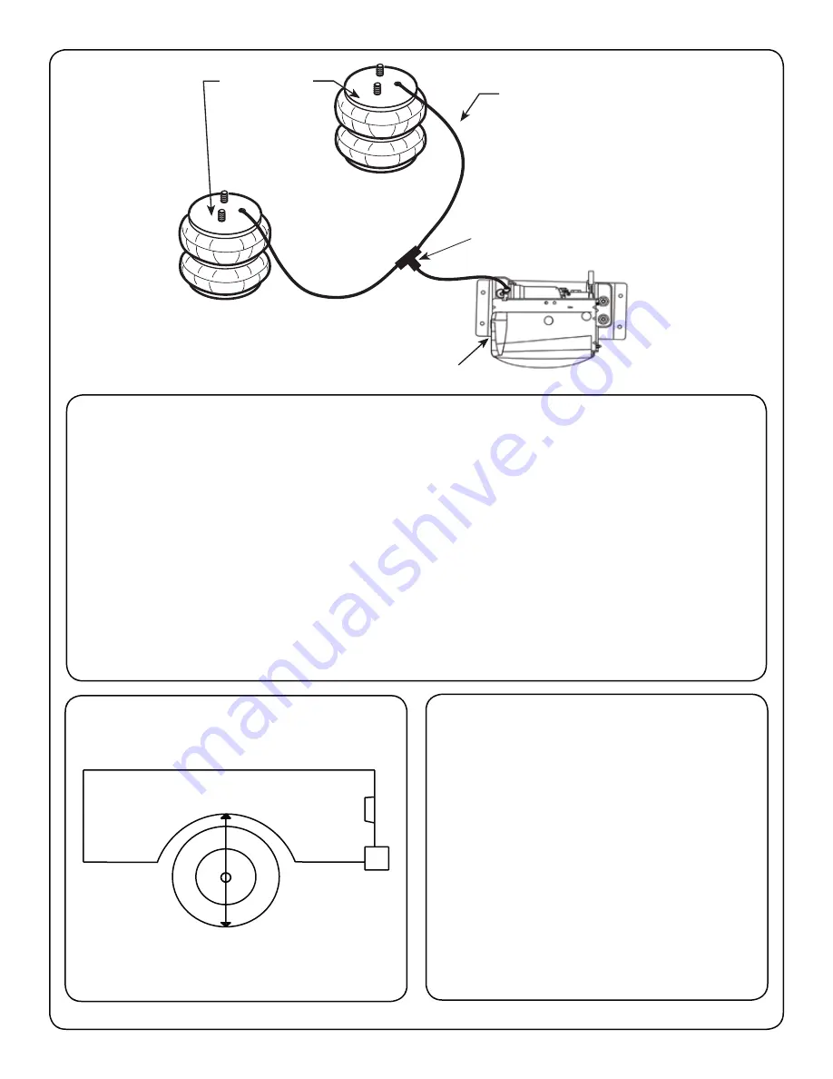
AIR LINE
AIR
SPRINGS
COMPRESSOR
AIR LINE “T” FITTING
15.
. Start at the Airspring fur-
thest from the compressor. Trim the airline so that the cut is clean and as square as possible.
$ :
the airspring to the compressor keeping it away the exhaust pipe and sharp edges. If it is neces-
sary to run the line over a sharp edge, use a supplied thermal sleeve over the airline to protect
it. The sleeve is installed by sliding it over the airline to the area where the line needs protected.
The airline should not be bent or curved sharply, this can cause the line to buckle or kink
.
; <=
to the compressor, trim off the excess and use it for the remaining air spring line to the compres-
& >?
>?
TIP:
&


