background image

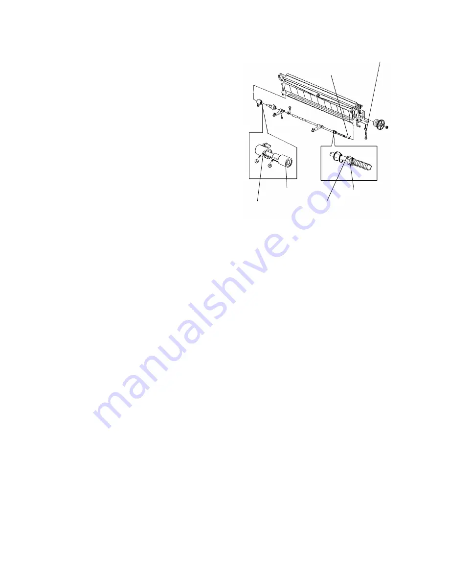
11. Assemble the pawl shaft assembly and

place it into the cleaning unit, sliding the
rear end of shaft into the hole in the rear
side plate.

NOTE: 1. When installing the cam holder

and the cam rider, align [A] with
[B] as shown in the figure.

2. Make sure that the spring end is

in the small hole on the rear
side plate.

12. Install the pawl shaft pin.

13. Push the spring collar to the rear and rotate

it one turn as shown in the figure.
Then set the collar on the pin.

NOTE: Make sure that the end of the

spring is correctly positioned in the
groove of the collar.

14. Reassemble the cleaning unit.


Spring End

Pawl Shaft Pin

Spring Collar

Pin

Cam Rider

Cam Holder

- 82 -

Содержание FT5034

Страница 1: ...SERVICE MANUAL FT5034C...

Страница 2: ...ENTS 1 INSTALLATION 2 2 OVERVIEW 7 3 COPY PROCESS 11 4 SECTION DESCRIPTIONS 13 5 SP MODE DIP SW TABLE 92 6 CALL SERVICE CONDITIONS 98 7 PREVENTIVE MAINTENANCE 105 8 TROUBLESHOOTING 114 9 ELECTRICAL DA...

Страница 3: ...1 INSTALLATION 1 1 INSTALLATION REQUIREMENTS 3 1 2 INSTALLATION PROCEDURE 4 2...

Страница 4: ...rea filled with dust and subjected to frequent strong vibration Avoid narrow space 10 m3 2 Access to Copier Place the copier near a power source providing clearance as shown The copier must be level w...

Страница 5: ...e copier as follows 1 From platen cover to front cover 2 Manual table 3 Feed guide cassette insert section 4 Transport guide plate 5 T S corona unit 6 Toner shield glass 7 Front loading cassette lever...

Страница 6: ...lever 2 Remove the charge corona unit together with the wire cleaner 1 screw 3 Remove the drum stay 1 knob and 1 screw The drum knob is reverse threaded 4 Pull out the drum protective sheet 5 Reinsta...

Страница 7: ...from red to green after 2 min 2 Lower the platen cover and enter 99 using the number keys and press the Start key Drum conditioning takes about 5 min 3 After the drum conditioning is finished open the...

Страница 8: ...2 OVERVIEW 2 1 SPECIFICATIONS 8 2 2 GUIDE TO COMPONENTS 9 7...

Страница 9: ...Enlargement Less than 3 5 seconds Enlargement Reduction Less than 5 0 seconds Photoconductor Selenium drum F type Development System Magnetic brush system Image Density Control Development Bias system...

Страница 10: ...2 2 GUIDE TO COMPONENTS 1 Operation Panel 9...

Страница 11: ...2 Indicator Panel 10...

Страница 12: ...3 COPY PROCESS 3 1 COPY PROCESS DIAGRAM 12 11...

Страница 13: ...ed on and at every 10th copy after that 6 PRE TRANSFER LAMP PTL The PTL illuminates the drum to remove all positive charge from the exposed areas of the drum This prevents the toner particles from bei...

Страница 14: ...CAL COMPONENT LAYOUT 16 4 4 PAPER FEED AND REGISTRATION 18 4 5 OPTICS 28 4 6 AROUND THE DRUM 44 4 7 DEVELOPMENT AND TONER SUPPLY 50 4 8 ID SENSOR AND PTL 62 4 9 IMAGE TRANSFER PAPER SEPARATION AND PAP...

Страница 15: ...Separation Corona Wire 14 Drum 15 Charge Corona Wire 16 Transfer Corona Wire 17 Erase Lamp 18 Development Unit 19 4th Mirror 20 Feed Roller By pass Feed 21 Toner Tank 22 Pick up Roller 23 Pressure Le...

Страница 16: ...F Belt Drive Motor Gear 11 DF Feed Roller 12 Bin Transfer Wheel 13 Bin Support Rack 14 Bin Support Pinion Gear 15 Bin Drive Motor Gear 16 Sorter Adapter Feed Motor Pulley 17 Sorter Adapter Drive Belt...

Страница 17: ...12 Door Switch 13 2nd Feed Clutch 14 Relay Roller Clutch 15 F L Front Loading Feed Clutch 16 F L Tray Paper End Sensor 17 Cleaning Solenoid 18 Main Power Relay 19 Main Switch 20 Power Supply Board 21...

Страница 18: ...Vacuum Fan 45 Erase Lamp 46 ID Sensor Board 47 PTL Pre Transfer Lamp 48 Registration Sensor Board 49 2nd Cassette Paper Size Sensor 50 1st Cassette Paper Size Sensor 51 By pass Table Sensor 52 By pass...

Страница 19: ...clutch the paper feed clutches are all magnetic clutches The CPU turns on the paper feed clutch for the required station at a programmed time after the Start key is pressed Upon receiving the signal...

Страница 20: ...ce The paper size sensors are actuated by a plate on the front of the cassette Each paper size has its own unique combination of notches in the actuator plate For the front loading feed station if pap...

Страница 21: ...e guides allow the release levers to move back up The cassette arm then presses up the cassette bottom plate until the paper contacts the paper feed roller 5 Registration The registration rollers have...

Страница 22: ...pad system To use a larger size than B4 at the by pass feed table the large cassette must be installed in order to support the trailing part of the paper When the by pass feed table is opened the pic...

Страница 23: ...r a photointerrupter is activated and the copier enters by pass feed mode The by pass feed mode is the same as interrupt mode When the by pass feed table is opened the copier stores the previous job s...

Страница 24: ...I 102 24A Size 4 I 102 22B Size 5 I 102 25A Paper End 1 I 102 23B Paper end detection Paper End 2 I 102 25B 1st Feed MC O 101 5A 2nd Feed MC O 101 3A By pass Feed MC O 101 10A F L Feed MC O 101 2A Rel...

Страница 25: ...e hub is positioned toward the rear on the shaft 4 Remove the friction pad holder by pressing the lower hooks using long nose pliers 5 Peel off the friction pad and stick a new pad on the friction pad...

Страница 26: ...with Mobil Temp 78 7 Reinstall the friction pad holder NOTE Be sure the legs of the friction pad holder are positioned under the spring loaded pad positioning mechanism The eccentric cam should be sec...

Страница 27: ...vel surface of the friction pad holder with Mobil Temp 78 9 Reinstall the friction pad holder on the holder bracket NOTE The eccentric cam should be secured in the original position referring to the m...

Страница 28: ...the following adjustment 1 Remove the cassette 2 Turn the eccentric cam A to adjust the friction pad pressure as shown in figures 1 and 2 NOTE If the eccentric cam groove is aligned vertically the gap...

Страница 29: ...tion ratios six reductions three enlargements and full size In addition it has a zoom function The user can change the reproduction ratio in one percent steps from 50 to 200 This machine has an automa...

Страница 30: ...racket As the lens motor is a stepper motor the rotation of the lens drive pulley moves the lens back and forth in discrete steps The lens home position sensor informs the optics CPU IC403 when the le...

Страница 31: ...closer together The plates block part of the light passing through the lens to keep the intensity of the light on the drum even 3 2nd Scanner Drive In order to provide the proper optical distance betw...

Страница 32: ...ricted at reproduction ratios of 156 200 This causes partial enlargement because the lens restricts exposure lamp movement ex Effective original area at 200 enlargement Copying can be in the range as...

Страница 33: ...maximum sample voltage and changes the development bias accordingly The exposure lamp voltage is constant equal to the voltage at the manual density level 4 regardless of the image density of the orig...

Страница 34: ...F OFF Nor mal OFF small OFF OFF OFF small OFF OFF Nor mal OFF OFF ON OFF ON ON OFF ON OFF ON ON ON ON TB 0 2 Pitch E 0 8 mm Pitch TB Vertical magnification Scanner speed E Lead edge erase R Lead edge...

Страница 35: ...f before replacement 1 Remove the exposure glass 2 Move the first scanner to the position where the rear frame is cut out 3 Remove the reflector cover 2 screws 4 Wrap a strip of paper around the expos...

Страница 36: ...1 Do not adjust vertically using the adjusting knob 2 If the adjustment is incorrect uneven image density or dirty background will appear on the copy image 4 2nd and 3rd Mirror Replacement 1 Remove th...

Страница 37: ...Replacement 1 Remove the top cover 12 screws 2 Remove the sub reflector 2 screws 3 Remove the upper seal at the front side 4 Free the lamp harness from the bracket 1 screw 5 Lift the 1st scanner thro...

Страница 38: ...nstall the mirror with the reflecting surface uppermost 2 Install the mirror with the cutout part facing down 3 Attach the spring plate to the non reflecting surface 11 Position the front spring plate...

Страница 39: ...ve the rear cover 3 screws and lower the PCB plate 2 screws 5 Remove the damper wheel 6 Loosen the wire clamp screw 7 Remove the lamp stabilizer bracket 1 screw 8 Move the 2nd scanner to the return po...

Страница 40: ...5 Lower side Wire Clamp 6 Lower track WP3 7 Inner track WP4 8 Three and half turns from lower to upper Scanner Drive Pulley 9 Outer track WP4 10 Lower track WP5 11 Inner track WP2 12 Outer track WP6...

Страница 41: ...scale 2 short screws and the exposure glass 4 Remove the rear cover 3 screws and lower the main board bracket 2 screws 5 Tape the scanner drive pulley and the wire pulleys A 6 Loosen the scanner driv...

Страница 42: ...ve wire in the left fork and wrap the wire around the lens drive pulley for three and half turns 2 Run the wire on the tension pulley and set the wire bead in the right fork 3 Set the tension spring 8...

Страница 43: ...be faintly visible on the copy when the 4th level of the density control is selected 1 Clean the optics mirrors lens reflectors exposure glass toner shield glass 2 Turn on the main switch and allow it...

Страница 44: ...rrupt key 4 key Interrupt key 6 Press the Start key 7 Adjust the ADS voltage to 3 0 0 06 V as displayed in the magnification indicator of the operation panel by using VR102 on the main board NOTE 1 Re...

Страница 45: ...en the C B power pack applies a high positive voltage 5 0 kV 7 5 kV The selenium coating receives a uniform positive charge 700 50 V as it rotates past the corona unit The main motor fan provides a sm...

Страница 46: ...drum TH 1 determines the proper rest time compensation and TH 2 controls the development bias voltage A Lead Edge Erase Margin 3 5 0 5 mm B Side Margins 2 2 mm each For full size copies the total of b...

Страница 47: ...once every ten cycles the center block of erase lamps turns off long enough for the sensor pattern to be developed 2 Side Erase Based on the paper size and on the reproduction ratio the LEDs turn on i...

Страница 48: ...n Ratio Data 0 off 1 on Ratio 1 2 3 4 5 6 7 8 9 10 11 12 13 14 15 16 17 50 53 1 1 1 1 1 1 1 1 1 1 1 1 1 1 1 1 0 54 57 1 1 1 1 1 1 1 1 1 1 1 1 1 1 1 0 0 58 60 1 1 1 1 1 1 1 1 1 1 1 1 1 1 0 0 0 61 63 1...

Страница 49: ...r the light intensity of the QL is slightly less than that of the PTL This is because of the darkness of the filter colors The cold cathode lamp has the characteristics of low power consumption and lo...

Страница 50: ...py image will be erased lead edge erase T4 1 23 seconds after the Start key is pressed mode erase begins T5 If full erase begins after 2 49 seconds of erase the charge turns off T6 The T S charge PCC...

Страница 51: ...ddles and transports it to the development roller Internal permanent magnets in the development roller attract the developer to the development roller sleeve The turning sleeve of the development roll...

Страница 52: ...is moved slightly toward the rear of the unit by the mixing vanes Part of the developer falls into the auger inlet and is transported to the front of the unit by the mixing auger 3 Drive Mechanism The...

Страница 53: ...to the background from being developed this prevents dirty background The development bias voltage is supplied from the power pack C B to the bias terminal via the bias terminal plate 1 Bias Control...

Страница 54: ...r increases the bias at the begining of each copy run to prevent variations in the image density of the first few copies produced The amount of bias increase is shown in the two tables below If the dr...

Страница 55: ...copy counter to 11 or more After turning the ready indicator on press the Start key and measure the bias voltage NOTE Read the bias after the 11th copy in order to get the value without any rest time...

Страница 56: ...toner supplied and can be changed by using SP mode 30 1 Detect Supply Mode P mode The main CPU checks toner density by directly detecting the image density If toner density is too low the toner supply...

Страница 57: ...than five seconds If Vsp becomes greater than 0 8 volt twice the CPU starts blinking the Add Toner indicator After the indicator starts blinking the operator can make up to 50 copies then copying is...

Страница 58: ...its output the bias for the copy image is applied T2 If the toner density is too low the toner supply clutch turns on 0 55 second after the scanner motor reverses The time is 0 98 second at the 30 su...

Страница 59: ...1 0 0 290 2 5 0 1 0 1 320 1 7 2 16 2 6 6 0 1 1 0 350 7 0 1 1 1 380 1 65 2 16 8 1 0 0 0 410 9 1 0 0 1 440 1 65 10 1 0 1 0 500 11 1 0 1 1 500 12 1 1 0 0 530 13 1 1 0 1 560 14 1 1 1 0 590 15 1 1 1 1 620...

Страница 60: ...ased by 90 volts 4 7 3 Replacement and Adjustment NOTE When removing or reinstalling the development unit apply force towards the right side to avoid scratching the drum 1 Developer Replacement 1 Open...

Страница 61: ...angle and dump out the developer that has collected at the ends of the development unit 7 Repeat the above steps until you have removed all of the developer NOTE If developer remains in the developme...

Страница 62: ...support bracket 3 screws 1 E ring and 1 nylon clamp 5 Remove the pulse generator disk 6 Remove the toner supply clutch from the drive shaft 7 Install a new toner supply clutch 8 Reassemble the copier...

Страница 63: ...r pattern is erased by an erase lamp After the latent image is developed but before the image is transferred to the copy paper the drum surface is illuminated by the pre transfer lamp This illuminatio...

Страница 64: ...er block of the erase lamps turns off A5 Lengthwise size long enough for the sensor pattern to be developed When the sensor pattern image on the drum is over the ID sensor the LED of the ID sensor tur...

Страница 65: ...nsity of the developer because it indicates the reflected light intensity from the sensor pattern The pattern is developed by using the present developer in the machine The toner density will be contr...

Страница 66: ...V When the toner is supplied the toner density becomes higher and the ID sensor pattern image becomes darker Consequently Vsp is lower than the reference value and the toner is not supplied 4 Abnormal...

Страница 67: ...gh strong 2 Exposure weak rapid 3 Drum Sensitivity slow high 4 Development Bias low light dark high low supplied no supplied high low return to the original condition Variation Factor Image Density Vs...

Страница 68: ...IGH OFF ON 30 ON OFF 45 OFF ON HIGHER ON ON 60 ON ON Set up procedure P Mode a Set SP mode 30 to 10 b Leave SP mode c DPS101 3 ON DPS101 4 OFF P mode 30 3 The toner density can be changed by the chang...

Страница 69: ...rmal full erase for the lead edge erase 0 18 second later T3 When checking the toner density the ID sensor LED turns on 1 20 seconds after the Start key is pressed and ID sensor output is sent to the...

Страница 70: ...ve the rear cover 3 screws 2 Lower the main board bracket 2 screws 3 Remove the registration clutch stopper 1 screw 4 Remove the ID sensor connector 1 screw 5 Slide out the pre transfer lamp 1 screw a...

Страница 71: ...the main board 5 Place five sheets of A3 paper on top of each other on the exposure glass and lower the platen cover 6 Hook up the positive lead of a multimeter to TP103 ID sensor output check on the...

Страница 72: ...ation corona wires apply an ac corona to the reverse side of the paper The stiffness and the weight of the paper then cause it to separate from the drum 4 9 2 Mechanical Parts 1 Overview The registrat...

Страница 73: ...pin on the cam drive gear rotates the cam wheel This wheel has six slots in which the pin catches so the cam wheel turns 1 6 of a revolution for each full turn of the cam drive gear The cam part of th...

Страница 74: ...r cover and lower the main board bracket 2 screws 7 Disconnect all the connectors of the T S PCC power pack and remove the power pack 1 screw 8 Remove the cam lever assembly 1 screw 9 Disconnect the v...

Страница 75: ...13 Remove the front of the transport unit as shown 1 E ring 1 spring and 1 shaft 14 Pull the right transport wheel and belt to the right and remove the transport wheel 15 Remove the transport belt 74...

Страница 76: ...de the cleaning unit As the brush turns inside the cleaning unit it rubs against a beater ridge which dislodges the toner particles The toner particles fall onto the toner collection coil The toner co...

Страница 77: ...the positively charged toner and removes about half of it from the drum This further reduces the load on the cleaning blade 3 Drive Mechanism The main chain drives the cleaning unit when the main mot...

Страница 78: ...g at each end to apply even pressure if it is mounted in this way The blade scraper is mounted in contact with the bottom side of the cleaning blade When pressure is applied to the cleaning blade it i...

Страница 79: ...ontact the drum in the same place but instead move slightly to the side on each copy cycle The pick off shaft and the cam rider are joined by a one way bearing Each time the pick off pawl solenoid tur...

Страница 80: ...it turns off 0 12 second after the fusing exit sensor turns off T3 The pick off pawl solenoid starts 1 49 seconds after the Start key is pressed and the pick off pawls contact the drum After 1 0 secon...

Страница 81: ...ck off pawls are kept away from the drum when removing the cleaning unit or serious drum damage will result 2 Cleaning Blade Replacement 1 Take out the cleaning unit See Cleaning Unit Removal 2 Remove...

Страница 82: ...ection coil cover 1 screw 3 Slide out the toner collection coil from the front of the cleaning unit NOTE Toner will fall out when the coil is pulled 4 Remove the pawl shaft pin from the pawl shaft 5 P...

Страница 83: ...e figure 2 Make sure that the spring end is in the small hole on the rear side plate 12 Install the pawl shaft pin 13 Push the spring collar to the rear and rotate it one turn as shown in the figure T...

Страница 84: ...ff to maintain the operating temperature Pressure roller The pressure roller presses the paper into contact with the hot roller The pressure comes from two pressure springs Thermistor The CPU monitors...

Страница 85: ...ween the two fusing rollers The release gear spring allows the release gear to move in and out This prevents the gears from being damaged if they should not engage correctly when the fusing unit is in...

Страница 86: ...nt any variation in the scanner motor speed or the exposure lamp intensity When the scanner starts moving in reverse fusing lamp control again shifts to ON OFF control 3 Service Call Conditions 1 Stat...

Страница 87: ...th your hands because finger oil marks may damage the lamp 3 Swing down the fusing exit assembly and unhook the pressure springs 4 Remove the harness support bracket 2 screws and 2 hooks 5 Remove the...

Страница 88: ...Remove the fusing unit and cover 2 screws 2 Swing down the fusing exit assembly and unhook the pressure springs 3 Remove the fusing knob and the oil pan 1 screw each 4 Remove the front pressure lever...

Страница 89: ...screw 3 Remove the thermofuse wire from the metal wire clamp 1 screw 4 Disconnect the thermofuse 1 connector and install the new thermofuse 6 Thermistor Replacement 1 Remove the fusing unit and the fu...

Страница 90: ...ocation A Feeding Section Location B Fusing Unit Location D Sorter Location E ADF After removing the misfed paper make sure that all units and levers are returned to their original positions and the f...

Страница 91: ...ice Call Conditions Self Diagnostic Code 61 1 Definition This code is generated if the CPU does not receive a pulse for longer than 1 second during a copy cycle 2 Symptoms When the Start key is presse...

Страница 92: ...s 2 Remove the 2 screws securing the operation panel to the inner panel brackets 3 Slide the operation panel toward the front and lift it off the side panel brackets 4 Disconnect the dc harness from t...

Страница 93: ...5 SP MODE DIP SW TABLES 5 1 SERVICE PROGRAM MODE 93 5 2 DIP SWITCH TABLES 96 5 3 INPUT CHECK MODE 97 92...

Страница 94: ...MODE NUMBER USING THE NUMBER KEYS THE SP MODE NUMBER AND 1 WILL BLINK ALTERNATELY IN THE COPY COUNTER RECALL ENTER Change the setting PRESS THE 0 OF THE NUMBER KEYS WHEN YOU WISH TO CHANGE THE SETTIN...

Страница 95: ...Toner Supply Mode 10 10 P MODE Detect Supply Mode 11 C MODE Fixed Supply Mode 33 ID Sensor Bias Color NOTE 6 10 10 Normal 590 volts 11 High 620 volts 34 Image Bias Up 10 10 Normal 11 The Development B...

Страница 96: ...ormed This procedure is required only when the copier malfunctions due to a damaged RAM board or when the RAM board is replaced CAUTION Memory all clear is done immediately after you press the 0 key t...

Страница 97: ...ON ON LARGE ON ON FOR PRODUCTION NORMALLY ON ON OFF ON OFF OFF ON OFF ON OFF OFF OFF OFF OFF NORMAL SMALL OFF OFF SMALL OFF OFF OFF ON OFF ON ON OFF ON OFF ON ON ON ON TB 0 2 Pitch E 0 8 mm Pitch 3 D...

Страница 98: ...ith this input check mode you have to leave the SP mode MODE 1 2 3 4 REMARKS Vsp 1 Vsg 1 While the key is hold down BIAS Voltage 1 While the 0 key is held down ID SENSOR Input Voltage 2 ADS Data 3 ADS...

Страница 99: ...6 CALL SERVICE CONDITIONS 6 1 CALL SERVICE CONDITION CODES 91 6 2 CALL SERVICE CONDITION DETAILS 92 98...

Страница 100: ...ion is not detected 28 Lens home position not on Displayed if the lens is moving towards enlargement and the H P sensor stays at a low signal level for longer than 3 7 seconds 29 Lens home position no...

Страница 101: ...ERVICE CONDITION DETAILS PROBLEM CAUSE ACTION STATUS 11 LAMP MALFUNCTION 1 LAMP REGULATOR MALFUNCTION 2 EXPOSURE LAMP OPEN 3 MAIN BOARD MALFUNCTION 1 Check if the exposure lamp is lit during stand by...

Страница 102: ...NER MOTOR MALFUNCTION 1 Replace the main board 2 Check the scanner motor and replace it if necessary STATUS 24 NO HOME POSITION SIGNAL 1 MAIN BOARD MALFUNCTION OPTICS CONTROL SECTION 1 Replace the mai...

Страница 103: ...output of the scanner motor If it is malfunctioning replace the scanner motor 2 Replace the main board 3 Check the voltage of the power source wall outlet STATUS 31 DRUM THERMISTOR BLOWN 1 DRUM THERMI...

Страница 104: ...POWER RELAY 12 15 220V FUSING UNIT CONNECTOR IS FUSING CONTROL BOARD CN1 8 LOW REPLACE THE POWER RELAY CHECK THE FUSING LAMP IS BLOWN CHECK THE FUSING UNIT CONNECTOR REPLACE THE OPERATION PANEL REPLAC...

Страница 105: ...d 4 If the voltage at 1 2 of CN2 on the main motor is not 220V replace the SSR of the PSU and if it is 220V replace the main motor STATUS 91 TOTAL COUNTER MALFUNCTION 1 TOTAL COUNTER MALFUNCTION 2 MAI...

Страница 106: ...7 PREVENTIVE MAINTENANCE 7 1 OVERVIEW 98 7 2 PM TABLE 99 7 3 EXPLANATION OF REGULAR PM 101 7 4 REGULAR PM PROCEDURE 103 105...

Страница 107: ...exchange of worn out parts 2 Removal of dirt to maintain good copy quality 3 Inspection and adjustment to maintain good copy quality 4 Lubrication 5 Replacement of defective parts 6 At service call d...

Страница 108: ...ace the friction pad and entrance seal mylar as a set for the front loading cassette 11 Registration rollers O O O Alcohol or water 12 Paper feed guide plate O O O Alcohol or water 13 Registration sen...

Страница 109: ...42 Exit brush O O O Drive unit 43 Drum drive belt Replace if necessary 44 Drive chain Mobil temp 78 45 Bushings Spindle oil Others 46 Exposure lamp voltage Check using input check mode at manual imag...

Страница 110: ...opy may become dirty Cleaning is required at regular intervals Around Drum Corona Wires Dirty corona wires may cause uneven image density They should be cleaned or replaced at regular intervals End Bl...

Страница 111: ...wls at regular intervals Fusing Entrance and Exit Guides Toner piling up on the guide plate will cause a dirty background on the copy Clean the guide plate at regular intervals ADF Transport Belt A di...

Страница 112: ...um in clean sheets of paper to protect it Around the drum every 40K 1 Clean the end blocks casing and transfer guide plate with a damp cloth and wipe them with a dry cloth 2 Clean the QL and PTL filte...

Страница 113: ...ers and friction pads Machine rear side every 40K 1 Clean the ID sensor and registration sensor with a blower brush 2 Inspect the drum drive belt Machine rear side every 80K 1 Lubricate the main drive...

Страница 114: ...Lubricate the oilless bushings using spindle oil Exterior unit Clean the covers Copy quality After performing drum conditioning for 10 copies turn off the DIP SW on the operation panel board and make...

Страница 115: ...8 TROUBLESHOOTING 114...

Страница 116: ...ly visible image will appear on the copy image However when the bias charge P P fails no image will appear 3 The development roller does not turn Due to slippage of the roller or a broken drive gear c...

Страница 117: ...Bias Voltage 1 Check the Development Roller 2 Check the Development Roller Gear 1 Check the charge corona wire 2 Check CN101 A17 on the main board goes from 5 to 0V 3 Check between conn 1 14 on the B...

Страница 118: ...r toner scattered when the inlet seal is deformed 2 The mirror and exposure glass are contaminated by oil 3 Toner concentration is too high If toner concentration is too high toner will be scattered i...

Страница 119: ...ck the lamp voltage It should be less than 160 V Lamp regulator output adjustment Dirty Background Charge Corona Toner Shield Glass Image Density too high Seal on the Dev Unit 2 1 Clean the toner shie...

Страница 120: ...e adjust VDE VDE 3 0 0 06V 1 Doctor Gap is too wide Deterioration of Drum Deterioration of Developer VDE high 1 Adjust the lamp regulator Voltage 2 Replace the drum 1 Check the doctor gap 1 Replace th...

Страница 121: ...ppears in non image areas The copied pattern changes depending on the reproduction ratio 1 Contamination of the mirrors and exposure glass Note If the image pattern does not change in any reproduction...

Страница 122: ...harge Corona Mirrors and Exposure Glass Exposure Lamp 1 Clean the mirror lens and exposure glass 1 Check for exposure lamp deterioration 2 Adjust the exposure lamp positon 1 Clean the charge corona wi...

Страница 123: ...ned with toner due to a defective inlet seal on the development unit 2 The lens and mirrors are dirty 3 The edge of the cleaning blade is damaged 4 An over concentration of toner causes the black stri...

Страница 124: ...2 1 Check the toner shield glass 2 2 Clean the surface of the mirrors 2 3 Check the cleaning blade 2 4 Check the image density 3 1 Check for scratches on the drum 3 1 Check for scratches on the hot r...

Страница 125: ...substance 1 Deformation of the PTL filter 2 Deformation of the ID sensor board 3 Deformation of the transfer separation guide plate An indistinct white line appears on the copy 1 The inlet seal on the...

Страница 126: ...e charge corona wire sharp white lines will appear on the copy Vertical White Lines Charge Corona Cleaning Blade Foreign Substance Check the cleaning blade PTL ID Sensor Toner Pile up T S Guide Plate...

Страница 127: ...e when the copier stops CASE 1 Cause If black lines appear at 151 mm from the leading edge of the paper Check 1 Check whether this black line appears at 151 mm intervals after making copies of other s...

Страница 128: ...g Blade Check the seals on the dev unit Check the erase lamp Check the Drum Drum Check for scratches on the drum Clean the cleaning blade and cleaning brush If not solved replace both the cleaning bla...

Страница 129: ...jitter appears on the copy It is especially noticeable in enlargement mode It may be caused by an incorrect voltage being supplied from the power supply unit 8 Scratch at 251 mm intervals Problem Caus...

Страница 130: ...work replace the drum 2 If there is a horizontal black line clean the drum dust it with setting powder and then perform drum conditioning 99 copies Jitter Scanner Drive Motor Scanner Drive Pulley Pow...

Страница 131: ...cur if the scanner lock plate is not mounted when transporting the copier Action Remarks 1 Check whether the scanners are parallel 2 Copy case 1 Raise the front side of the 1st scanner Copy case 2 Low...

Страница 132: ...ing on the type of original used 2 The image density of black solid areas is too high 5 The toner supply ratio is greater than the actual usage If 45 supply in detect supply mode is selected and a sol...

Страница 133: ...magnification counter Mark the toner supply shaft Press the Start key after the main switch is turned OFF and ON 2 6 revolutions per copy Check the toner supply clutch Is VSG 4 0 0 2 Adjust VR101 on...

Страница 134: ...ensor To decrease toner density set DIP SW 101 3 OFF and 101 4 ON Make 10 20 copies in A3 size with the platen cover open Clean inside copier especially the PTL and ID sensor After turning the main sw...

Страница 135: ...sity of solid areas is too low 2 The charge current is too high If the charge current is increased in order to improve solid black images Vsp is decreased lowering the image density 2 Solid black area...

Страница 136: ...ification counter Mark on the toner supply Clutch Shaft Turn on DIP SW 101 2 on the main board Press the Start key 2 6 revolutions per copy Check the toner supply clutch Is VSG 4 0 0 2 Adjust VR101 on...

Страница 137: ...in the size magnification counter going down No toner inside the toner cartidge Check the main control board Make 20 copies with the drum conditioning switch ON and check the revolution END 1 Yes No...

Страница 138: ...1 The nip width is too narrow 2 The fusing temperature is too low 3 Thermistor malfunction Action Remarks 1 Replace the pressure spring on the fusing unit Deviation between front and rear must be les...

Страница 139: ...urn position During copying the scanner is driven to the return position 1 Scanner motor malfunction 2 Optics control board malfunction Action Remarks 1 Measure the power source voltage when the main...

Отзывы: