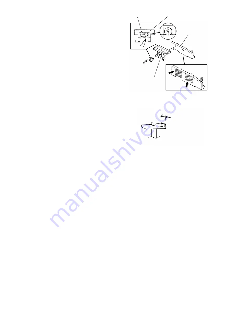
5. Mark the position of the eccentric cam
groove on the friction pad holder.
6. Remove the friction pad holder from the
holder bracket (1 screw and 1 eccentric
cam).
7. Peel off the entrance mylar and the friction
pad and stick new ones on the friction pad
holder.
NOTE: Check that the friction pad is 0.05
to 0.35 mm below the surface of
the front lip.
Make sure that the overlapping
length of the entrance mylar on the
friction pad (P) is 2.5 to 3 mm.
8. Clean and grease the swivel surface of the friction pad holder with Mobil Temp
78.
9. Reinstall the friction pad holder on the holder bracket.
NOTE: The eccentric cam should be secured in the original position referring to
the mark made in step 5).
10. Clean and grease the swivel surface of the holder bracket with Mobil Temp 78.
11. Reattach the friction pad assembly to the F/L feeding station.
NOTE: Be sure the legs of the friction pad holder are positioned under the
spring loaded pad positioning mechanism. Make sure that the pressure
spring is properly positioned and the friction pad assembly swivels
smoothly.
Eccentric Cam
Friction Pad Holder
Holder Bracket
Entrance Mylar
MT78
P
2.5 ~ 3.0 mm
- 26 -
Содержание FT5034
Страница 1: ...SERVICE MANUAL FT5034C...
Страница 3: ...1 INSTALLATION 1 1 INSTALLATION REQUIREMENTS 3 1 2 INSTALLATION PROCEDURE 4 2...
Страница 8: ...2 OVERVIEW 2 1 SPECIFICATIONS 8 2 2 GUIDE TO COMPONENTS 9 7...
Страница 10: ...2 2 GUIDE TO COMPONENTS 1 Operation Panel 9...
Страница 11: ...2 Indicator Panel 10...
Страница 12: ...3 COPY PROCESS 3 1 COPY PROCESS DIAGRAM 12 11...
Страница 93: ...5 SP MODE DIP SW TABLES 5 1 SERVICE PROGRAM MODE 93 5 2 DIP SWITCH TABLES 96 5 3 INPUT CHECK MODE 97 92...
Страница 99: ...6 CALL SERVICE CONDITIONS 6 1 CALL SERVICE CONDITION CODES 91 6 2 CALL SERVICE CONDITION DETAILS 92 98...
Страница 115: ...8 TROUBLESHOOTING 114...


