background image

Safety Installation Information 

1.  READ and FOLLOW all instruction. 
2.  The gate opener is intended for use with Class I vehicular 
swing gates. 
Class I denotes a vehicular gate opener (or system) dwellings, 
or a garage or parking area associated therewith. 
Install the gate opener only when the opener is appropriate for 
the construction and the usage class of the gate. 
3.  Gate opening system designers, installers and users must 
take into account the possible hazards associated with each 
individual application. Improperly designed, installed or 
maintained systems can create risks for the user as well as the 
bystander. Gate system design and installation must reduce 
public exposure to potential hazards. All exposed pinch points 
must be eliminated or guarded. 
4.  A gate opener can create high levels of force during 
normal operation. Therefore, safety features must be 
incorporated into every installation. Specific safety features 
include safety sensors. 
5.  The gate must be properly installed and work freely in 
both directions prior to the installation of the gate opener. 
6.  The gate must be installed in a location so that enough 
clearance is provided between the gate and adjacent structure 
when opening and closing to reduce the risk of entrapment. 
Swinging gates shall not open into public access areas. 
7.  The opener is intended for use only on gates used for 
vehicles. Pedestrians must be supplied with a separate access 
opening. The pedestrian access opening shall be designed to 
promote pedestrian usage. The pedestrian access shall be 
located such that persons will not come in contact with the 
moving vehicular gate. 


8.  Pedestrians should never cross the pathway of a moving 
gate. The gate opener is not acceptable for use on any 
pedestrian gate. Pedestrians must be supplied with a separate 
pedestrian access. 
9.  For an installation utilizing non-contact sensors (safety 
sensors), see product manual on the placement of non-
contact sensors (safety sensors) for each type of application. 

a. 

Care shall be exercised to reduce the risk of nuisance 

tripping, such as when a vehicle trips the safety sensor while 
the gate is still moving. 

b. 

One or more non-contact sensors (safety sensors) shall 

be located where the risk of entrapment of obstruction exists, 
such as the perimeter reachable by a moving gate or barrier. 
10.  Never mount any device that operates the gate opener 
where the user can reach over, under, around or through the 

gate to operate the controls. Controls are to be placed at least 
6’ (1.8m) from any part of the moving gate. 


11.  Controls intended to be used to reset an operator after 2 
sequential activations of the entrapment protection device or 
devices must be located in the line of sight of the gate, or easily 
accessible controls shall have a security feature to prevent 
unauthorized use. Never allow anyone to hang on or ride the 
gate during the entire travel of the gate. 
12.  Each gate opener is provided with two safety warning 
placards. The placards are to be installed on the front and back 
of the gate where they are plainly visible. The placards may be 
mounted using cable ties through the four holes provided on 
each placard. 
All warning signs and placards must be installed where visible 
in the area of the gate. 


13.  To AVOID  damaging gas, power, or other underground 
utility lines, contact underground utility locating companies 
BEFORE digging. 
SAVE INSTRUCTION. 


14.

  Do not permit children to play on or around the gate and 

keep all controls out of their reach.

Содержание GTR062

Страница 1: ...follow all warnings and instructions before installation and use The gate opener must be powered by 2 PCS 12VDC 12Ah batteries connected in series Never connect solar panel to the control board direct...

Страница 2: ...hould never cross the pathway of a moving gate The gate opener is not acceptable for use on any pedestrian gate Pedestrians must be supplied with a separate pedestrian access 9 For an installation uti...

Страница 3: ...ons Features Specifications Input 120V 60Hz or 230V 50Hz Motor voltage 24VDC Power 2 80W Current 3A Actuator speed 16mm s Max actuator travel 385mm Ambient Temperature 20 50 4 F to 122 F Protection cl...

Страница 4: ...obstruction during gate opening Reverse in case of obstruction during gate closing Built in adjustable auto close 0 100 seconds Built in max Motor running time MRT for multiple safety protection 40 s...

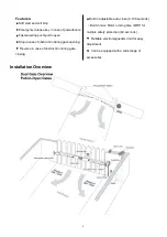
Страница 5: ...e anchors are not provided When mounting the Post Brackets to wooden posts a larger size washer or metal plate should be used between the bolts and the wooden post to ensure the stability of the faste...

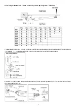
Страница 6: ...through the center hole of the post bracket and post pivot bracket as shown Place a 10 washer 10 lock washer and M10 nut on the bottom of the bolt and hand tighten 2 Attach the gate bracket and post b...

Страница 7: ...nterclockwise 4 With the opener fully retracted and with the gate in the fully open position for Pull to Open installation or fully closed position for Push to Open installation place the gate opener...

Страница 8: ...f there is not at least 2 5cm of clearance or if the opener and the Post Pivot Bracket are binding rotate the Post Pivot Bracket and or move the Post Bracket Assembly to obtain the minimum clearance a...

Страница 9: ...ach bolt with one 10 washer one 10 lock washer and one 10 nut 9 Attach the gate brackets to each gate by inserting two M10 x 75 bolts through the gate brackets and the drilled holes in the gates Faste...

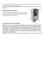
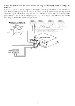
Страница 10: ...x Connection of the power supply The gate opener must be powered by 2 PCS 12VDC batteries connected in series NOT INCLUDED If you choose the batteries as the power source Marine or Automotive Type Bat...

Страница 11: ...should be at least 30W x 24V The gate opener can works for 10 cycles if there is no other accessory except photocell electric lock push button alarm lamp connected to the control board The capacity o...

Страница 12: ...15 Connection of the control board...

Страница 13: ...tocell Beam System PBS optional Use a 2 core cable to connect the terminal of the photocell s emitter to the 24 1 terminal the terminal to the GND 3 terminal Also the and terminals of the photocell s...

Страница 14: ...rd The GND terminal of the receiver should be wired to the 12 terminal of the control board 11 Wired Keypad optional The RED wire of the wired keypad should be connected into the 11 terminal The BLACK...

Страница 15: ...nds the CODE LED will flash for 3 seconds and then to OFF Now the remote has been programmed successfully NOTE The button of the remote control should be pressed and hold for more than 2 seconds while...

Страница 16: ...ON and then release the button Then press OK button on keypad and CODE LED will flash for 3 seconds and then be OFF which indicates the keypad has been programmed successfully You can use the default...

Страница 17: ...unction disabled Set the switch 2 to ON to enable the auto close function Factory default setting is OFF DIP Switch 3 Enable disable open interval between the master and slave gate opener ON Open inte...

Страница 18: ...time of the gate opener Turn the potentiometer clockwise to increase the auto close time and turn it counter clockwise to decrease the auto close time The auto close time can be adjusted steplessly fr...

Страница 19: ...power supply of the gate opener is connected or not The batteries or a 24Vdc AC DC power supply must be used to power the gate opener 2 Check the fuse 3 Check if the wire connection of the power suppl...

Страница 20: ...to OFF Check if the jumper wire between the EDGE and GND terminal is loosening or not The gate stop when on the way of opening or closing Flash quickly for 10 seconds and then back to OFF Flash quickl...

Страница 21: ......
Отзывы: