17
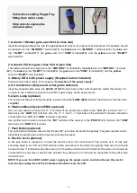
9. Exit Wand (optional)
The
BLACK
wire of the exit wand should be connected into the “#5” terminal.
The
BLUE
wire of the exit wand should be connected into the “#6” terminal.
The
RED
wire of the exit wand should be connected into the “#11” terminal.
The
GREEN
wire of the exit wand should be connected into the “#12” terminal.
The sensitivity adjustment board should be wired to the
GREEN
wire and the
YELLOW
wire of the wand. No
matter the polarity.
10. Wireless Exit Wand (optional)
The
“NO”
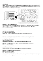
terminal of the receiver should be wired to the “#6” terminal of the control board.
The
“COM”
terminal of the receiver should be wired to the “#5” terminal of the control board.
The
“PWR”
terminal of the receiver should be wired to the “#11” terminal of the control board.
The
“GND”
terminal of the receiver should be wired to the “#12” terminal of the control board.
11. Wired Keypad (optional)
The
RED
wire of the wired keypad should be connected into the “#11” terminal.
The
BLACK
wire of the wired keypad should be connected into the “#5” terminal.
The
PURPLE
wire of the wired keypad should be connected into the “#5” terminal.
The
BLUE
wire of the wired keypad should be connected into the “#4” terminal.
12. External receiver (optional)
The
RED
wire of the external receiver should be connected into the “#11” terminal.
The
BLACK
wire of the external receiver should be connected into the “#5” terminal.
The
BROWN
wire of the external receiver should be connected into the “#4” terminal.
Note: Using of the exit wand, keypad and external receiver would cause the battery exhausted quickly.
Big capacity of battery and big power of solar panel (if the solar panel is used as main charger) is
required if you want to use either of them.
Содержание GTR062
Страница 12: ...15 Connection of the control board...
Страница 21: ......


