Rice Lake WLS-C Скачать руководство пользователя страница 28

24

WLS-C Wheel Loader Scale

4.0

Operation

The WLS-C system is based on the measurement of the lift cylinder piston pressure (by means of the pressure
transducer) and the calculation of the raise speed (with angle sensor).
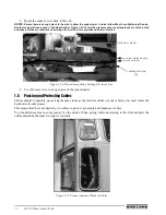
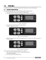
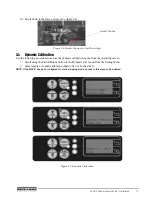
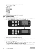
4.1

Making a Weighment

Use the following procedure to weigh a load based on the Active Weighing mode.

Dynamic Weighing with 2 Proximity Sensors on Forklifts

Following the initial lift off the ground, maintain a constant lifting speed during the complete weighing cycle.
The WLS-C will begin calculating the load automatically when the first proximity is activated, and will be
completed when the second proximity is then activated. The buzzer will start beeping when the first proximity is
activated, and will continue until the completion of the weighing cycle. The partial load will then be added
automatically to the total weight.

Dynamic Weighing with 2 ASC or Proximity Sensors on Front Loaders

Fill the bucket, begin lifting maintaining fully open raise function and a constant RPM speed during the complete
weighing cycle. The WLS-C will begin calculating the load automatically when the ASC sensor angle start
weigh angle is or when the first proximity is activated, and will be completed when the ASC sensor end weigh
angle or second proximity is then activated. The buzzer will start beeping when the sensors are activated, and
will continue until the completion of the weighing cycle. The partial load will then be added automatically to the
total weight.

NOTE: Avoid weighing with the machine tilted sideways, and/or sloping forward or backward. Avoid sudden and/or
abrupt movements during the weighing operation.

4.2

Setting a New Tare

Setting a new tare may be necessary when changing the actual bucket, changing the viscosity of the hydraulic oil
in the circuit, or when some material accumulates in the bucket, which cannot be dislodged during normal
dumping operation. It’s a known fact that the quantity of material accumulated in a bucket, after the first few
cycles, stays more or less constant, therefore by setting a new tare, it enables zeroing the extra weight of the
bucket, weighing only the material effectively dumped in the body of the truck. It is advisable to verify the status
of the tare prior to beginning loading operations, by performing an empty weighing; in the eventuality that the
partial weight is not “0”carry out the tare zeroing as described below. Repeat this operation a few times during
the day to compensate for the hydraulic oil temperature variations.

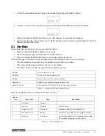
Zeroing Existing Tare

1. With an empty bucket, press and hold the Tare/Sel button until the lower LED is illuminated, the Tare

value will be zeroed.

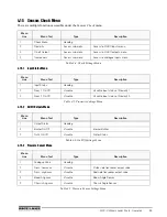
Acquiring a new Tare:

1. Perform an empty weighing based on the active weighing mode shown on the WLS-C screen. See

“Making a Weighment” on page 24. for more information.

The screen will display a value for the partial weight.

2. Press and release the Tare/Sel button. 

The upper LED will illuminate and the new Tare value will be acquired.

NOTE: To view the actual Tare value go to the User Menu by press and holding the Print/Enter button.

Содержание WLS-C

Страница 1: ...115203 WLS C Wheel Loader Scale Installation User Manual To be the best by every measure...

Страница 2: ......

Страница 3: ...Button Functions 12 2 1 Indicator Display 12 2 2 Indicator Buttons 13 3 0 Calibration 14 3 1 Entering Calibration Mode 14 3 2 Parameters 15 3 3 Angle Calibration 15 3 3 1 Calibration procedure 16 3 4...

Страница 4: ...f product related topics at no cost Visit www ricelake com webinars 4 14 Time Setting Menu 32 4 15 Sensors Check Menu 33 4 15 1 Input Status Menu 33 4 15 2 On Off Outputs Menu 33 4 15 3 Pressure Senso...

Страница 5: ...mbing connector or relative component Always make certain that all moving parts have been locked and check for any residual pressure when disconnecting any hydraulic plumbing Always let the bucket or...

Страница 6: ...ure 1 2 find the desired angle and tighten the handle Figure 1 2 Bracket screwed in place Wire Connect To PT1 Pressure transducer PT2 Second pressure transducer optional Prox1 Angle sensor on chassis...

Страница 7: ...upplied to attach the sensor to the flange block The kit comes with a few common fittings which fit the majority of wheel loaders It may be required to locate special fittings for the installation See...

Страница 8: ...lls off easily The fittings shown in Figure 1 5 Figure 1 6 and Figure 1 8 can be connected directly to the valve of the machine The weld on fitting Figure 1 7 can be used on the steel tubing of the cy...

Страница 9: ...WLS C Wheel Loader Scale Installation 5 Figure 1 10 Flange Welded to Hydraulic Line at Desired Angle Figure 1 11 Sensor Mounted at Non Recommended Angle Figure 1 12 Sensor Mounted at Recommended Angle...

Страница 10: ...em in such a way that the lifting reference notch activates the first proximity switch and that it remains active even when the second has been activated If the weighing system is running properly the...

Страница 11: ...WLS C Wheel Loader Scale Installation 7 Figure 1 14 Location of Installed Proximity Sensor Figure 1 15 Installation Location of First Switch 40 50 cm...

Страница 12: ...e necessary because the relative angle between the chassis and the boom is used to perform the weighing computation Figure 1 16 Sensor Placement 1 Using two to three 1 beads weld the angle sensor s mo...

Страница 13: ...he arm and must parallel on the boom There are 3 bolts on the angle sensor 1 on top and 2 on the bottom The angle sensor should be installed so that the 1 bolt side faces up and the side with 2 bolts...

Страница 14: ...ng Existing Electrical Line 4 Tie off excess wire in an open area of the wheel loader 1 5 Passing and Protecting Cables Cables should if possible pass along the same route as the electrics cables of y...

Страница 15: ...ted Correctly Do not mount the cables too close to the motor unless they are well insulated If you use clips to fix the cables down remember not to tighten them too much Very often cable breakage is d...

Страница 16: ...nd displays the software version and the date of the latest upgrade For example WS06_05 WS06_XX 28 2 2010 DD MM YY Figure 2 1 WLS C Software Version and Date of Last Update This screen is visible for...

Страница 17: ...n adds the partial load to the total 2 Partial Minus Partial zeroing button 3 Print Enter Press and hold for 3 seconds to access Operation menu Press and release once to print ticket optional printer...

Страница 18: ...he Partial Minus button to reach the Setting Menu Figure 3 1 Setting Menu 3 Press and release the Print Enter button to enter the menu The display indicates CAL PIN 0 Figure 3 2 Enter Calibration PIN...

Страница 19: ...n of angle sensor on the boom LEFT RIGHT press and release the Print Enter button to change the mounting side Left is standard Act Angle The actual value of relative angle or the difference between th...

Страница 20: ...hat end value Figure 3 7 Bucket Position for Start Angle Value 7 Lower the bucket about one foot from the ground level See Figure 3 8 8 Scroll to the Get Reset Angle menu 9 Press and release the Print...

Страница 21: ...owing procedure to access the dynamic calibration menu from the operating screen 1 Scroll using the Partial Minus button to the Dynamic Cal menu from the Setting Menu 2 Select empty or loaded calibrat...

Страница 22: ...e refer ET1 xxxx xxxxx ET1 xxxx xxxxx Allows viewing the complete empty calibration 1 table it is possible to view two values the left value corresponds the index table whereas the value on the right...

Страница 23: ...Time Time elapsed during the lift obviously the lower this value the greater the speed of the lift TP1 value Indicates the piston s pressure transducer reading TP2 value Indicates the rod s pressure t...

Страница 24: ...er of lifts performed at decreasing speed which will correspond to the number of points recorded in loaded calibration 2 table refer LT2 xxxx xxxxx LT2 xxxx xxxxx Allows viewing the complete loaded ca...

Страница 25: ...changes The asterisk will disappear 6 Scroll to another page of the menu or return to the operation menu by pressing and holding the Tare Sel button to the previous menu 3 8 Calibration Menu There ar...

Страница 26: ...etting Setting lifting cylinder s thickness for calibration 1 set in cm 2 Cylinder 2 xxxx Setting Setting lifting cylinder s circumference for calibration 2 set in cm 2 Rod 2 xxxx Setting Setting cyli...

Страница 27: ...he regenerative valve is On or Off 2 Save Command Saving permanently all modifications to parameters Menu Line Menu Text Type Description 1 Dynamic Setting Text 2 Empty Cal Access to sub menu Access t...

Страница 28: ...added automatically to the total weight NOTE Avoid weighing with the machine tilted sideways and or sloping forward or backward Avoid sudden and or abrupt movements during the weighing operation 4 2 S...

Страница 29: ...ter button to access the User menu 2 Using the Partial Minus button scroll down to the Weighing menu and press and release the Print Enter button to disable the weighing The green LED will go out on t...

Страница 30: ...dent calibrations This is typically used when the machine is equipped with 2 different lifting devices for example bucket and forks Use the following procedure to select the desired calibration mode 1...

Страница 31: ...onds to enter the User menu 2 Scroll down using the Partial Minus button until you see the Contrast menu 3 Follow the Setting New Values on page 30 procedure to modify the contrast value which can be...

Страница 32: ...utton until you see the Time Setting menu Figure 4 8 Time Setting 3 Press and release the Print Enter button to select the time 4 Use the Partial Minus button to scroll to each sub menu then use the p...

Страница 33: ...Outputs To select the Out 4 sub menu press and release the Print Enter button Buzzer to visualize the status WLS C internal buzzer On when active Out 4 to visualize the printer s power supply status i...

Страница 34: ...r button An asterisk will appear on line 1 above the value to be modified 2 Modify the value of each figure by pressing and releasing the Tare Plus or Partial Minus button to change the value USER Men...

Страница 35: ...nus in the system where The first column refers to the line of the display in which the text is written The second column describes the text shown on the display The third column describes the type of...

Страница 36: ...u Access to diagnostics menu allowing visualizing proximity and outputs status and to read transducers values 2 Setting Menu Access sub menu Access to calibration menu restricted to system s installer...

Страница 37: ...Type Description 1 Input Status Heading 2 Proxy 1 On Off Visualize Visualize input status of Proximity 1 2 Proxy 2 On Off Visualize Visualize input status of Proximity 2 Table 4 5 Proximity Settings...

Страница 38: ...5 mm width Due to its lightness and compact size it can be easily fitted into a wide range of applications The WLS C roll paper printer includes customized programming capability making it capable to...

Страница 39: ...aud Rate 600 to 38 400 bps Receiver buffer 128 byte Flash memory 32K Graphic memory 1 logo of 348 x 85 dot Power supply 10 30 VDC Current consumption During printing 600mA idle 20mA Dimensions 146 x 8...

Страница 40: ...36 WLS C Wheel Loader Scale Figure 5 3 Printer Dimensions 64 5 96 146 112 88 2...

Страница 41: ...the nonconformity actually exists and was not caused by accident misuse neglect alteration improper installation improper repair or improper testing RLWS shall be the sole judge of all alleged non con...

Страница 42: ...Friday and 8 a m to 12 noon on Saturday CST Telephone Sales Technical Support 800 472 6703 Canadian and Mexican Customers 800 321 6703 International 715 234 9171 Immediate Emergency Service For immedi...

Страница 43: ......

Страница 44: ...PN 115203 12 10...

Отзывы: