


10
WLS-C Wheel Loader Scale
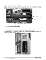
3. Route the sensor’s wire back to the cab.
NOTES: Ensure there is enough slack in the wire to allow the support arm to raise fully without over-tightening the wire.
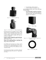
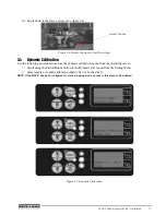
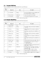
Route along a stationary area of the wheel loader. Figure 1-20 shows the pressure sensor and angle sensor wires routed
between a stationary cylinder and existing electrical line; this provides optimal protection.
Figure 1-20. Wires Routed Along Existing Electrical Line.
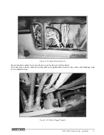
4. Tie off excess wire in an open area of the wheel loader.
1.5
Passing and Protecting Cables
Cables should, if possible, pass along the same route as the electrics cables of your vehicle, or at least where the
hydraulic circuitry passes.
This means that there are basically two cables to protect: proximity and transducer cables.
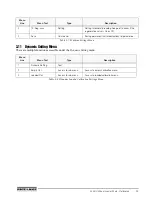
You should always leave some leeway for the cables. When giving full-lock steering to the left and right, the
cables should not become too tight or too slack.
Figure 1-21. Proper Amount of Slack in Cables
stationary cylinder
pressure and angle
sensor wires
existing electrical
line
Содержание WLS-C
Страница 1: ...115203 WLS C Wheel Loader Scale Installation User Manual To be the best by every measure...
Страница 2: ......
Страница 40: ...36 WLS C Wheel Loader Scale Figure 5 3 Printer Dimensions 64 5 96 146 112 88 2...
Страница 43: ......
Страница 44: ...PN 115203 12 10...


