


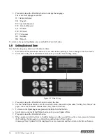


22
WLS-C Wheel Loader Scale
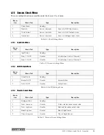
3.9
Password (PIN) Menu
There are multiple functions accessible under the
Password (PIN)
menu.
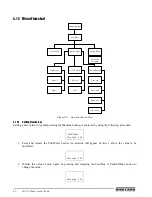
3.10 Machine Setting Menu
There are multiple functions accessible under the
Machine Setting
menu.
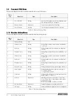
Menu
Line
Menu Text
Type
Description
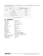
1
2
CAL. PIN XXXX
Setting
Insert the PIN to gain access to the calibration menu.
See “Setting New Values” on page 21.
2
Enter to Confirm
Command
Press Enter to confirm the PIN setting.
2
Access Denied
Viewing
This message is displayed if the PIN is incorrect.
Table 3-6. Password Settings Menu
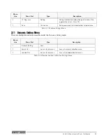
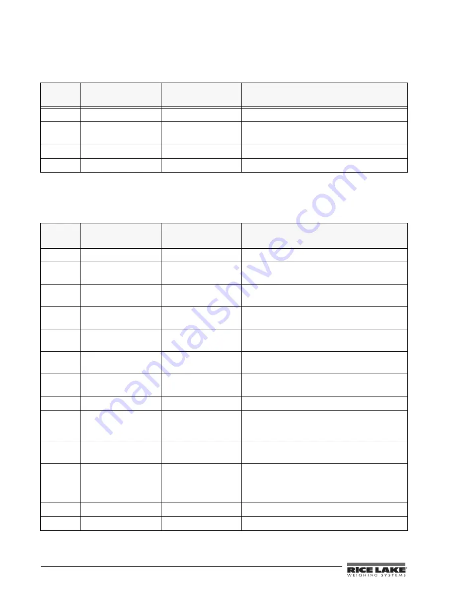
Menu
Line
Menu Text
Type
Description
1
Machine Setting
Text
2
Cylinder 1 xxxx
Setting
Setting lifting cylinder’s circumference for calibration
1, set in cm.
2
Rod 1 xxx
Setting
Setting cylinder rod’s circumference for calibration 1,
set in cm.
2
Thickness1 xxxx
Setting
Setting lifting cylinder’s thickness for calibration 1, set
in cm.
2
Cylinder 2 xxxx
Setting
Setting lifting cylinder’s circumference for calibration
2, set in cm.
2
Rod 2 xxxx
Setting
Setting cylinder rod’s circumference for calibration 2,
set in cm.
2
Thickness2 xxxx
Setting
Setting lifting cylinder’s thickness for calibration 2, set
in cm.
2
Round Val. xxxx
Setting
Setting rounding off value of partial weight. Default = 0
2
Active Angle x
Setting
Setting number for active angle sensor, range 0-1.
0 = Proximity Switch
1 = Angle Sensor (Default)
2
n.Decimals
Setting
Setting number of decimals for both partial and total
weight, range 0-3. Default = 2
2
Unit Print
Command
Selecting units of measure (0-none, 1-Kg, 2-Tons,
3-Lb., 4-Short Tons, 5-Cubic Meters) which will be
printed on the ticket.
NOTE: Only available if a printer is installed.
2
Del Ticket Num.
Command
Zeroing the progressive number on the ticket.
2
Use Reg. x
Setting
Enable or disable the regenerative valve management.
Table 3-7. Machine Settings Menu
Содержание WLS-C
Страница 1: ...115203 WLS C Wheel Loader Scale Installation User Manual To be the best by every measure...
Страница 2: ......
Страница 40: ...36 WLS C Wheel Loader Scale Figure 5 3 Printer Dimensions 64 5 96 146 112 88 2...
Страница 43: ......
Страница 44: ...PN 115203 12 10...


