


51
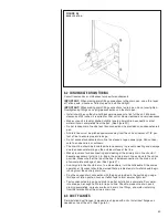
13. Final installation check. Be sure the motor is installed as follows.
a. Set the motor into the blower housing as originally provided from the manufactur-
er.
b. Do not allow the motor mount to cover the motor vent openings.
c. Do not attach the motor mount to the motor electronics compartment.
d. The motor connectors should be straight down.
e. Have appropriate drip loops formed in the harnesses.
14. Restore 230 volt power to the system. Verify that the new motor control module
works properly.
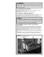
13.9 BLOWER WHEEL REPLACEMENT
With the blower assembly removed and the motor assembly removed (see above
instructions), remove the two screws holding the blower wrap (cutoff) to the blower
sides.
IMPORTANT:
It is not necessary to remove heating ele ment(s), if provided, to remove
the blower wheel.
• With wrap (cutoff) screws removed, cut off end of blower wrap will spring up. Lifting
wrap blower wheel is removed through the discharge opening in the blower housing.
• To replace, make sure wheel is oriented properly with hub to the opposite side from
the motor. Lift blower wrap and insert blower wheel through discharge opening in the
blower housing.
• Hold blower wrap down into position and replace two screws holding blower wrap to
blower sides.
• See motor replacement and blower assembly instructions for remaining assembly
procedure.
14.0 REPLACEMENT PARTS
Any replacement part used to replace parts originally supplied on equipment must be
the same as or an approved alternate to the original part supplied. The manufacturer will
not be responsible for replacement parts not designed to physically fit or operate within
the design parameters the original parts were selected for.
These parts include but are not limited to: Circuit breakers, heater controls, heater limit
controls, heater elements, motor, motor capacitor, blower relay, control transformer,
blower wheel, filter, indoor coil and sheet metal parts.
When ordering replacement parts, it is necessary to order by part number and include
with the order the complete model number and serial number from the unit data plate.
(See parts list for unit component part numbers).
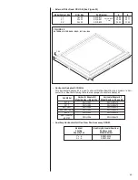
15.0 ACCESSORIES - KITS - PARTS
• Combustible Floor Base RXHB-17, RXHB-21, RXHB-24 (for standard units)
for
downflow applications, see section of this manual covering combustible floor base.
Combustible Floor
Model Cabinet Size
Base Model Number
17
RXHB-17
21
RXHB-21
24
RXHB-24
Содержание RH1V2417STANJA
Страница 54: ...54 FIGURE 44 COMFORT CONTROL2 SYSTEM AIR HANDLER WIRING DIAGRAM H2V...
Страница 55: ...55...
Страница 56: ...56 CM 0115...